Welded diaphragm valve

Active Publication Date: 2009-10-01
ENTEGRIS INC
View PDF18 Cites 14 Cited by
  • Summary
  • Abstract
  • Description
  • Claims
  • Application Information

AI Technical Summary

Benefits of technology

[0009]In one aspect, a diaphragm valve includes a valve body defining an inlet passage, an outlet passage, and a fluid chamber with an inner wall and an open side. Each of the inlet passage and the outlet passage form an opening in the inner wall so that the inlet passage, the outlet passage and the fluid chamber are fluidly communicable with each other. The valve may further include a valve seat portion surrounding the inlet passage opening in the fluid chamber and a flexible diaphragm assembly with a valve portion facing into the fluid chamber. The flexible diaphragm assembly is selectively shiftable between at least a valve closed position wherein the valve portion is sealingly engaged with the valve seat portion to block fluid flow through the valve, and a valve open position wherein the valve portion is spaced apart from the valve seat to enable fluid flow through the valve. An actuator assembly may be operably coupled with the flexible diaphragm assembly for selectively positioning the flexible diaphragm assembly in each of the valve open and the valve closed positions. The diaphragm assembly is welded to the valve body in a continuous weld to prevent the leakage of fluids around the diaphragm assembly. In some embodiments,

Problems solved by technology

A drawback of previous valve designs is that fluid leaks sometimes occur between the interface of the diaphragm assembly and the valve body, or between the interface of body or housing components.
Since the fluids used in the sem

Method used


Image

  • Welded diaphragm valve
  • Welded diaphragm valve
  • Welded diaphragm valve

Examples


Embodiment Construction

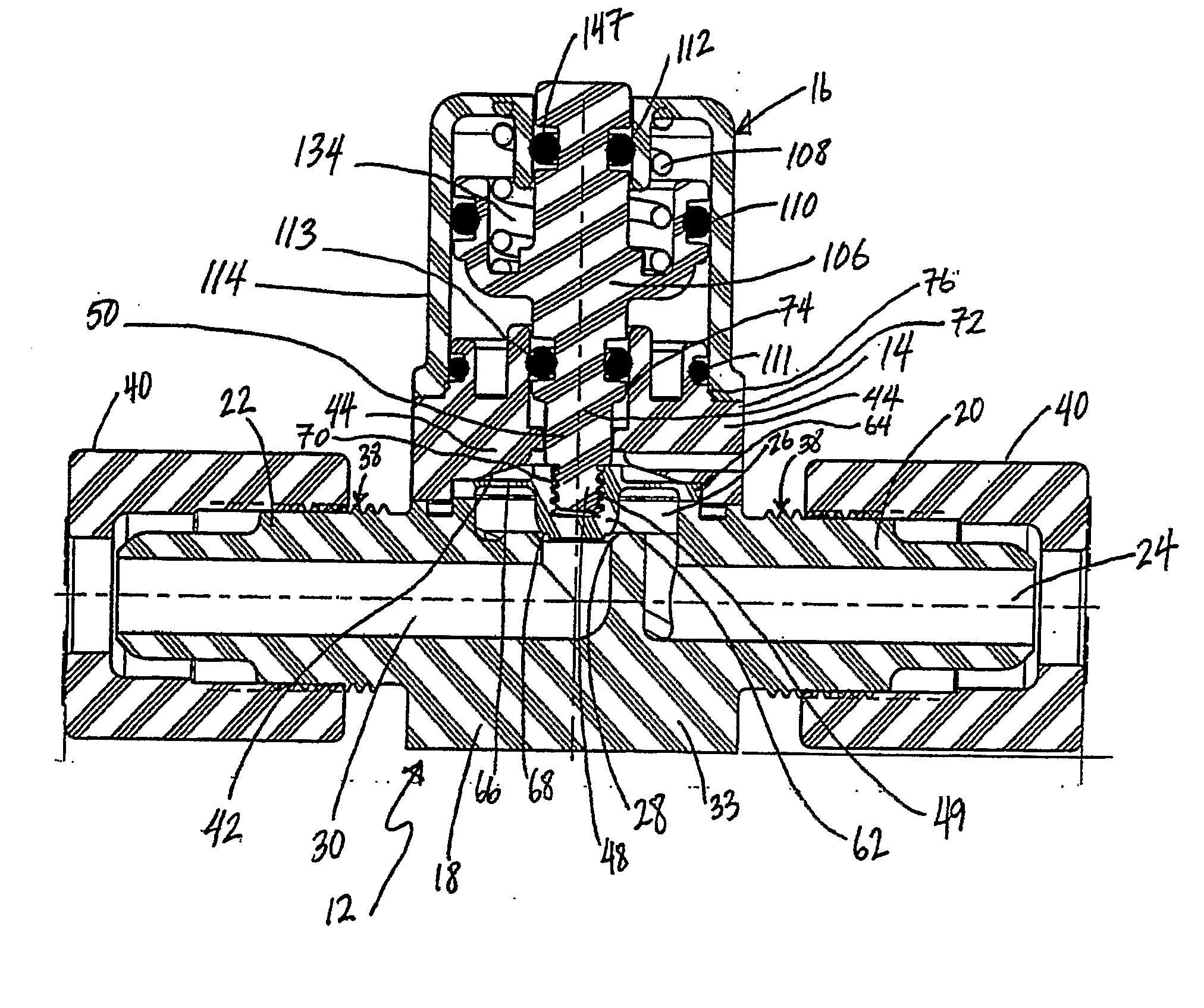
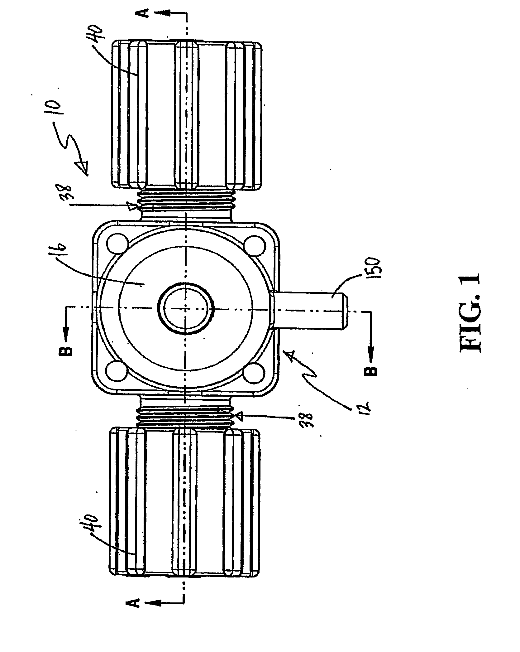
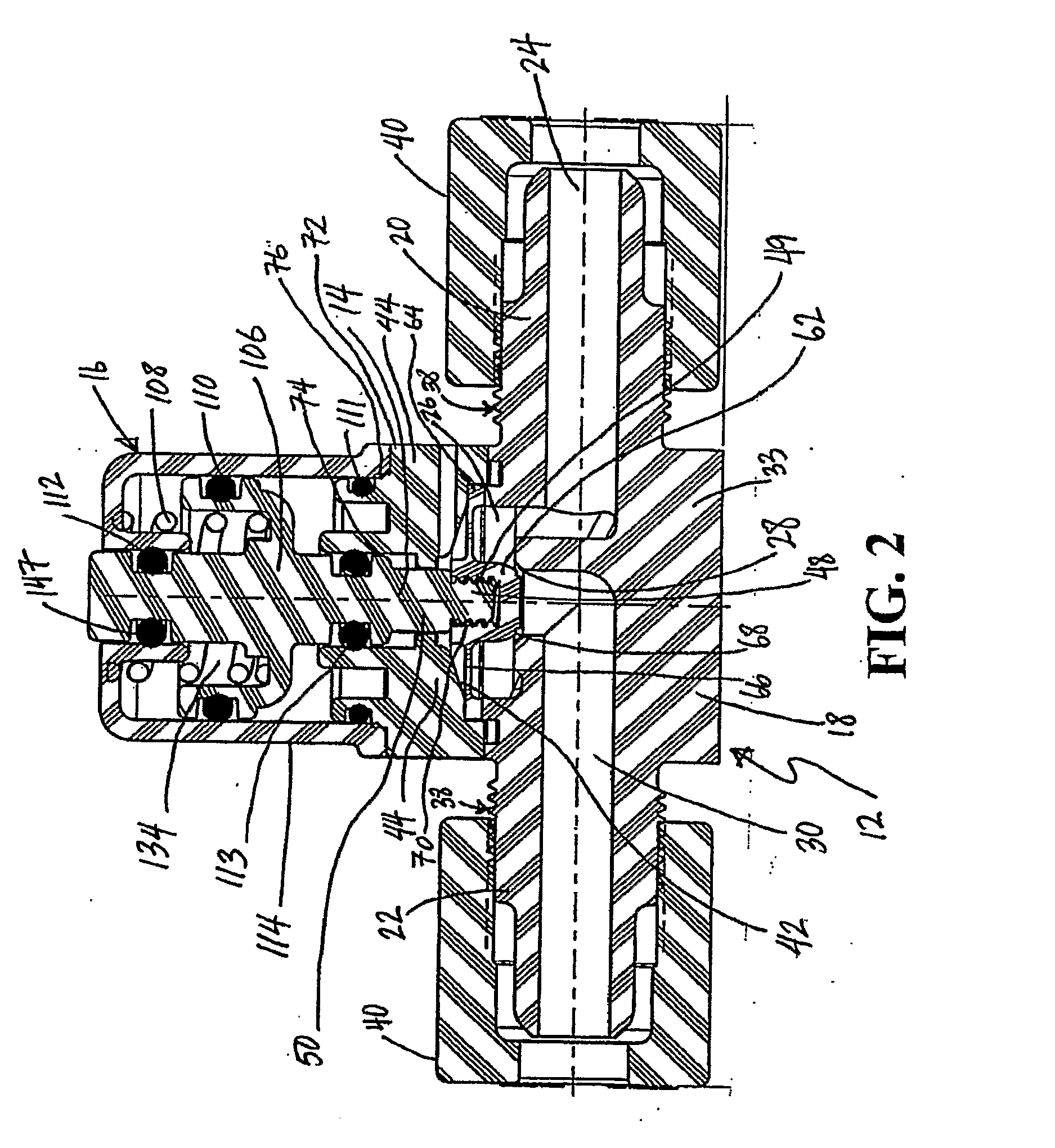
[0017]A valve 10 generally includes a body 12, a diaphragm assembly 14, and an actuator assembly 16. The body 12 has a central portion 18 with a pair of projecting nipples 20, 22. An inlet passage 24 extends from the nipple 20 into the central portion 18, turning upward and terminating in a fluid chamber 26. A valve seat 28 surrounds the termination of the inlet passage 24 in the fluid chamber 26. An outlet passage 30 extends from the fluid chamber 26 through the central portion 18 and the nipple 22. Each of the nipples 20, 22 has a threaded region 38 for receiving a threaded compression fitting sleeve 40 so that the valve 10 may be attached to piping or tubing (not depicted). Alternatively, of course, any other type of fitting or connection may be used to connect piping or tubing to the valve 10, including flare connections, straight threaded connections, or welding.

[0018]Diaphragm assembly 14 includes a primary diaphragm assembly 42 and a diaphragm retainer 44. In general, any dia...


PUM

PropertyMeasurementUnit
Flexibilityaaaaaaaaaa

Abstract

A diaphragm valve including a valve body, a diaphragm assembly and an actuator assembly having a housing body that isolates the actuator from the ambient atmosphere. The diaphragm assembly is welded to the valve body to reduce and/or eliminate fluid leakage around the diaphragm assembly. Additionally or alternatively, the housing body for the actuator assembly may be welded to the valve body to reduce fluid leakage. The welding may be performed using ultrasonic welding techniques.

Description

RELATED APPLICATIONS[0001]The application claims the benefit of U.S. Provisional Application No. 60 / 756,829, hereby fully incorporated herein by reference.FIELD OF THE INVENTION[0002]The present invention generally relates to valves, and more specifically to diaphragm valves having welded components.BACKGROUND OF THE INVENTION[0003]Various types of valves are used in the semiconductor industry to transport fluids, including highly caustic fluids. It is important that these valves do not cause quiescent or dead spots in the fluid flow course, which could cause the fluid to become stagnant and degrade or could trap solids resulting in the contamination of the fluid. In addition, it is important that the number of potential leakage sources or seals be kept to a minimum due to the highly caustic fluids often used in the semiconductor industry.[0004]These valves must be made of materials highly resistant to the caustic fluids. Contact with metal parts is generally to be avoided. The comp...

Claims


Application Information

Patent Timeline
IPC IPC(8): F16K1/08F16K1/44F16K1/48F16K31/50F16K41/12B21D51/16
CPCF16K27/0236Y10T29/49405F16K31/1262F16K27/102Y10T137/6055Y10T137/5994F16K41/12
Inventor LEYS, JOHN A.SCHLEICHER, MIKE
Owner ENTEGRIS INC
Why Eureka
Try Eureka