Method for controlling operation of a linear vibration motor

a linear vibration motor and operation method technology, applied in the direction of motor/generator/converter stopper, dynamo-electric converter control, electric motor speed/torque regulation, etc., can solve the problem that the timing at which an electric current is fed to the winding of the electromagnet becomes too late to efficiently supply the electric current, and it is difficult to save cost and reduce the size of the circuit. cost-effective and efficient

Inactive Publication Date: 2009-10-01
PANASONIC CORP
View PDF8 Cites 23 Cited by
  • Summary
  • Abstract
  • Description
  • Claims
  • Application Information

AI Technical Summary

Benefits of technology

[0004]In view of the above, the present invention provides a linear vibration motor operation control method capable of performing the operation control by which an electric current can be fed to a winding in a cost-effective and efficient manner.
[0005]In accordance with an aspect of the present invention, there is provided a method for controlling operation of a linear vibration motor including a stator formed of an electromagnet with a winding or a permanent magnet, a vibrator provided with a permanent magnet or an electromagnet with a winding and a control unit for controlling a driving current supplied to the winding of the electromagnet, the linear vibration motor being configured to reciprocate the vibrator relative to the stator, the method including: providing a non-energization period during

Problems solved by technology

In contrast, if an attempt is made to sufficiently lengthen the non-energization period, the timing at which an electric current is fed to the winding o

Method used


Image

  • Method for controlling operation of a linear vibration motor
  • Method for controlling operation of a linear vibration motor
  • Method for controlling operation of a linear vibration motor

Examples


Embodiment Construction

[0014]Hereinafter, a linear vibration motor and a method for controlling the operation thereof in accordance with an embodiment of the present invention will be described with reference to the accompanying drawings which form a part hereof.

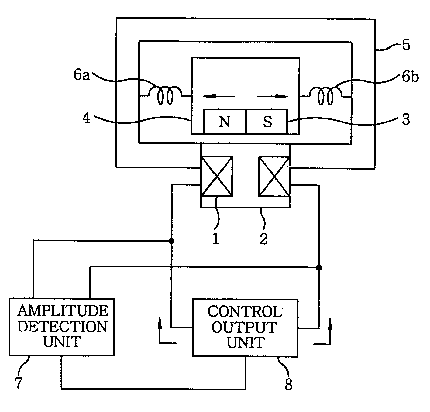
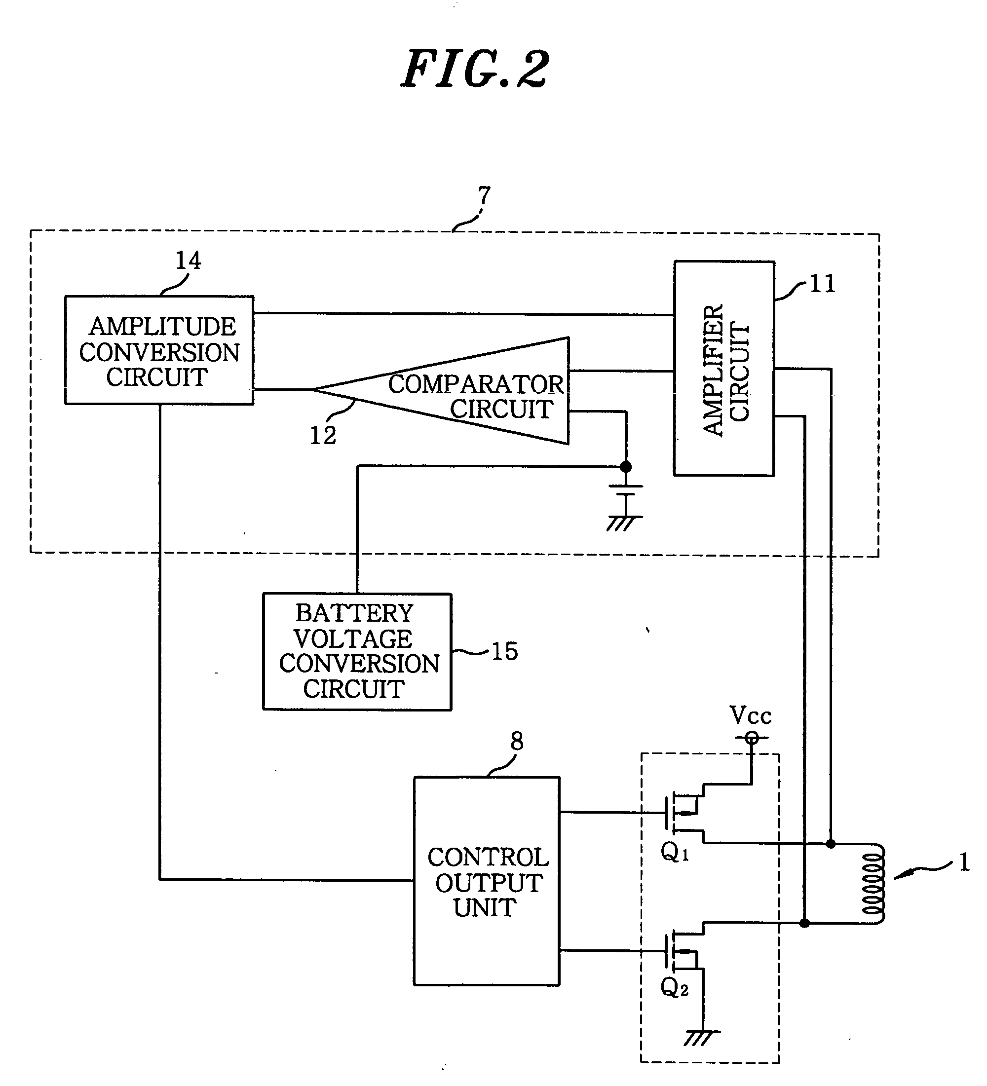
[0015]Referring to FIG. 1, a linear vibration motor in accordance with the embodiment of the present invention includes a stator 2 with a winding 1, a vibrator 4 with a permanent magnet 3, a frame 5 for holding the vibrator 4, springs 6a and 6b retained between the vibrator 4 and the frame 5, an amplitude detection unit 7 for detecting the vibration amplitude of the vibrator 4 based on the electromotive voltage induced in the winding 1 and a control output unit 8 for PWM (pulse width modulation)-controlling the driving current fed to the winding 1 based on the detection results of the amplitude detection unit 7. As shown in FIG. 2, the amplitude detection unit 7 includes an amplifier circuit 11 for amplifying the voltage between the opposite ends ...


PUM


Abstract

A linear vibration motor includes a stator formed of an electromagnet with a winding, a vibrator provided with a permanent magnet and a control unit for controlling a driving current supplied to the winding of the electromagnet. The linear vibration motor is configured to reciprocate the vibrator relative to the stator. A method for controlling operation of the linear vibration motor includes: providing a non-energization period during which no driving current flows through the winding of the electromagnet, the non-energization period being equal to greater than a ¼ cycle; detecting an electromotive voltage induced in the winding as the vibrator makes vibrating movement within the non-energization period; detecting the displacement, velocity or acceleration of the vibrator based on the electromotive voltage thus detected; and controlling the driving current supplied to the winding based on the displacement, velocity or acceleration of the vibrator thus detected.

Description

FIELD OF THE INVENTION [0001]The present invention relates to a method for controlling the operation of a linear vibration motor preferably applicable to a reciprocating electric shaver and designed to cause a movable body to make reciprocating movement.BACKGROUND OF THE INVENTION[0002]Conventionally, there is known a linear vibration motor that includes a stator formed of an electromagnet or a permanent magnet, a vibrator provided with a permanent magnet or an electromagnet and a control unit for controlling the driving current supplied to the winding of the electromagnet, the vibrator being reciprocatingly vibrated relative to the stator. In the linear vibration motor, there is a need to detect the amplitude displacement, velocity and acceleration of the vibrator in order to keep the amplitude constant. In this viewpoint, the conventional linear vibration motor has a non-energization period during which to detect the amplitude displacement, velocity and acceleration of the vibrato...

Claims


Application Information

Patent Timeline
IPC IPC(8): H02K33/00H02P25/06
CPCH02P25/027H02P25/032H02P27/06Y10S388/9072
Inventor KASHIWABARA, MINORUIBUKI, YASUO
Owner PANASONIC CORP
Why Eureka
Try Eureka