Link plate for a bicycle chain

a technology for bicycle chains and links, applied in the direction of driving chains, chain elements, belts/chains/gearrings, etc., can solve the problems of increasing noise, affecting transmission smoothness, and prior art's strength, so as to achieve easy and fast assembling or disassembly of the chain, high strength and anti-disengagement

Inactive Publication Date: 2009-10-01
TIEN HSIN INDS
View PDF69 Cites 16 Cited by
  • Summary
  • Abstract
  • Description
  • Claims
  • Application Information

AI Technical Summary

Benefits of technology

[0004]Accordingly, the primary object of the present invention is to provide a link plate for a bicycle chain, wherein the structure is simple so tha

Problems solved by technology

First, the prior art doesn't overcome the problem of disengagement.
Second, the prior art has the problem of strength.
Third, th

Method used


Image

  • Link plate for a bicycle chain
  • Link plate for a bicycle chain
  • Link plate for a bicycle chain

Examples


Embodiment Construction

[0012]In order that those skilled in the art can further understand the present invention, a description will be provided in the following in details. However, these descriptions and the appended drawings are only used to cause those skilled in the art to understand the objects, features, and characteristics of the present invention, but not to be used to confine the scope and spirit of the present invention defined in the appended claims.

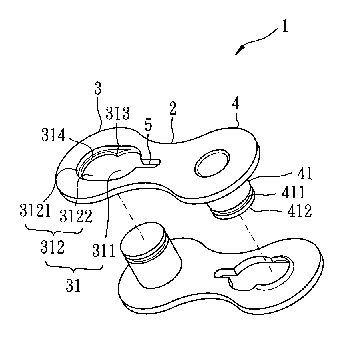
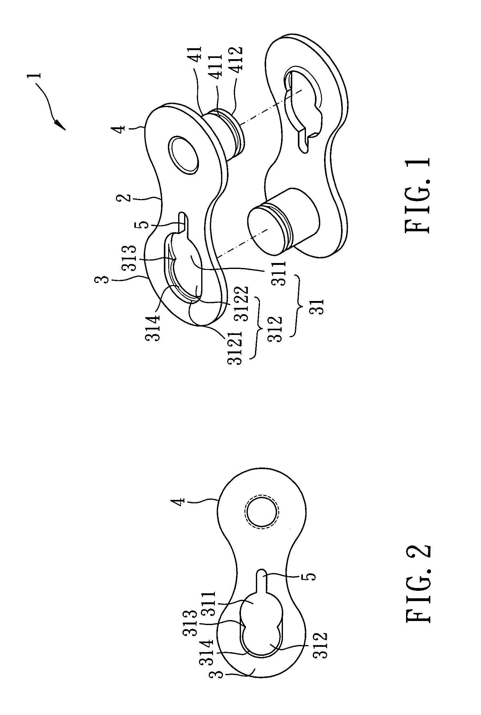
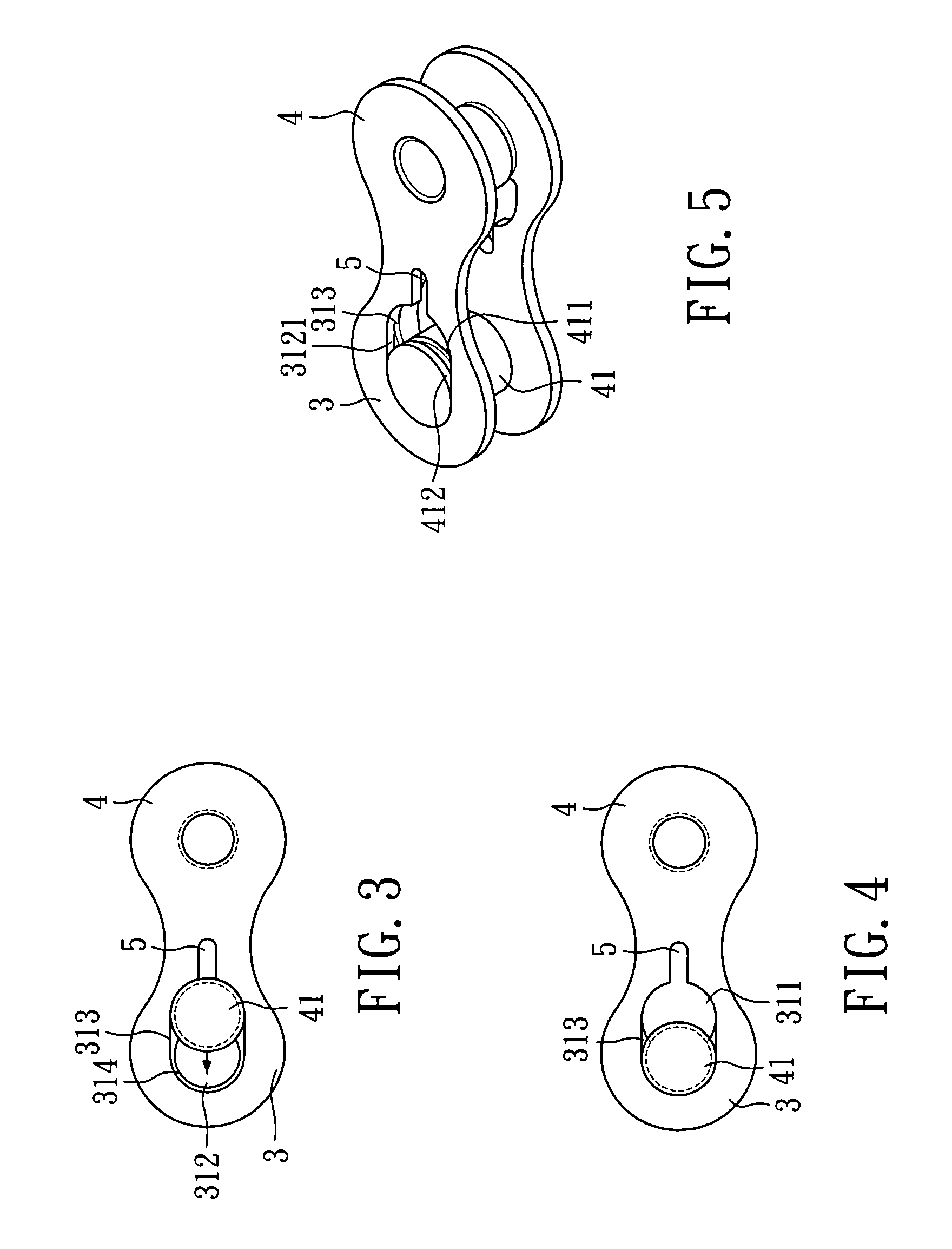
[0013]With reference to FIGS. 1 and 5, a link plate assembly of the present invention is illustrated. The link plate assembly includes a pair of link plates 1.

[0014]Referring to FIGS. 1 and 2, each of the link plates 1 includes a plate 2 and a pin 41. The plate 2 includes a first end 3 and a second end 4. The first end 3 forms an installation hole 31 and an elongated opening 5. The installation hole 31 includes a first aperture 311 and a second aperture 312. A diameter of the second aperture 312 is less than a diameter of the first aperture 311 and...


PUM


Abstract

A link plate for a bicycle chain comprises a plate having a first end and a second end. The first end includes an installation hole and an elongated opening. The installation hole includes a first aperture and a second aperture connected to the first aperture. A peak portion is defined between the first aperture and the second aperture to prevent movement of a pin from the second aperture to the first aperture easily. The elongated opening is connected to the first aperture to expand the installation hole slightly as the pin moves from the first aperture to the second aperture.

Description

FIELD OF THE INVENTION[0001]The present invention relates to a link plate for a bicycle chain, and particularly to a high strength link plate assembly which minimizes the possibility of accidental disengagement and is easy to assemble and disassemble.BACKGROUND OF THE INVENTION[0002]Referring to U.S. Pat. No. 5,291,730, “knuckle connector for connecting end knuckles of a chain strand” is disclosed, in that a knuckle connector is provided, which includes a pair of link units, each of which has a link pin and an oval-shaped link plate formed with a circular through-hole on one end and a retaining hole on an opposite end. The link pin has a head secured in the through hole and a tail end formed with a peripheral channel. The link pin of one of the link units extends through a pin hole formed in a corresponding one of the end knuckles such that the peripheral channel initially extends into a large insert part of the retaining hole in the link plate of a remaining one of the link units. ...

Claims


Application Information

Patent Timeline
IPC IPC(8): F16G15/12
CPCF16G13/06
Inventor CHIN, CHIH-CHUNG
Owner TIEN HSIN INDS
Why Eureka
Try Eureka