Shift control apparatus for automatic transmission

a technology of automatic transmission and control apparatus, which is applied in the direction of instruments, vehicle sub-unit features, transportation and packaging, etc., can solve the problems of difficult accurate detection, and achieve the effect of easy strain detection, low cost and simple structur

Inactive Publication Date: 2009-10-01
AISIN AW CO LTD
View PDF11 Cites 18 Cited by
  • Summary
  • Abstract
  • Description
  • Claims
  • Application Information

AI Technical Summary

Benefits of technology

[0015]In a preferred embodiment, the shift control apparatus further includes: an inertia phase detecting unit that detects a start of an inertia phase, based on a change in the torque value detected by the fixed gear torque detecting unit. In this embodiment, the torque change command unit is a torque down command unit that issues a command for performing a torque down as the torque change, responsive to detection of the start of the inertia phase by the inertia phase detecting unit. Therefore, by detecting the change in the value for torque acting on the fixed gear, it becomes possible to detect the start of the inertia phase quickly and accurately, thereby enabling the torque change to be performed at an appropriate timing.
[0016]The fixed gear torque detecting unit is composed of: a strain detecting sensor that detects strain between the fixed gear and the transmission case caused by the torque acting from the input shaft side; and a torque value calculating unit calculates the value for torque acting on the fixed gear, based on the strain detected by the strain detecting sensor. Therefore, for example, a strain gauge of a simple structure and comparatively low cost can be used as the strain detecting sensor. Further, because a structure for easily detecting the strain between the fixed gear and the transmission case is obtained by, for example, directly adhering the strain gauge on the fixed gear, it is possible to detect the torque value used for detecting the inertia phase with an extremely simple structure.
[0017]According to another aspect of the present invention, the speed change mechanism includes: a decelerating planetary gear set that outputs decelerated rotation, i.e. rotation that is decelerated from the rotational speed of the input shaft; a planetary gear unit that has four rotary elements including an output element connected to an output shaft of the speed change mechanism; two decelerating clutches that, when engaged, transmit rotation of the decelerating planetary gear set, respectively, to two of the rotary elements of the planetary gear unit; and an input clutch that, when engaged, transmits rotation of the input shaft to one of the rotary elements of the planetary gear unit, thereby achieving five or six forward speeds. The fixed gear is a gear that is constantly held stationary (without rotation) in the decelerating planetary gear set. Therefore, by using a comparatively simple structure based on merely a strain detecting sensor or the like that is attached to the fixed gear when assembling the speed change mechanism, the change in the input torque can be directly and accurately detected by, for example, detecting the inertia phase early and accurately, and that detection can be used, for example, to prevent erroneous learning in learning control.

Problems solved by technology

However, because the inertia phase serving as a trigger to start the torque reduction is detected as an occurrence of the rotational speed change, accurate detection is difficult.

Method used


Image

  • Shift control apparatus for automatic transmission
  • Shift control apparatus for automatic transmission
  • Shift control apparatus for automatic transmission

Examples


Embodiment Construction

[0027]A preferred embodiment of the present invention will now be described below with reference to FIGS. 1 to 8.

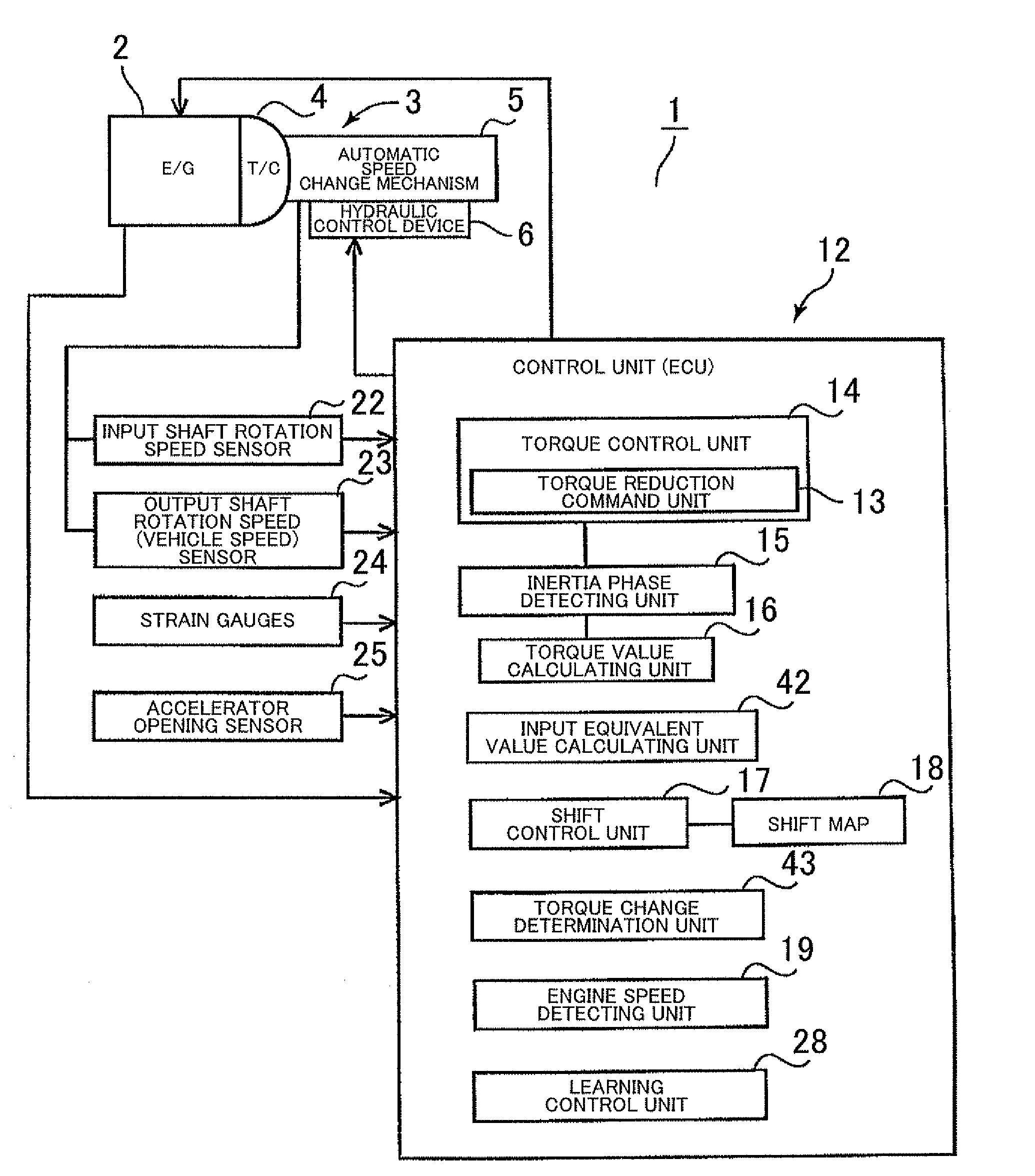
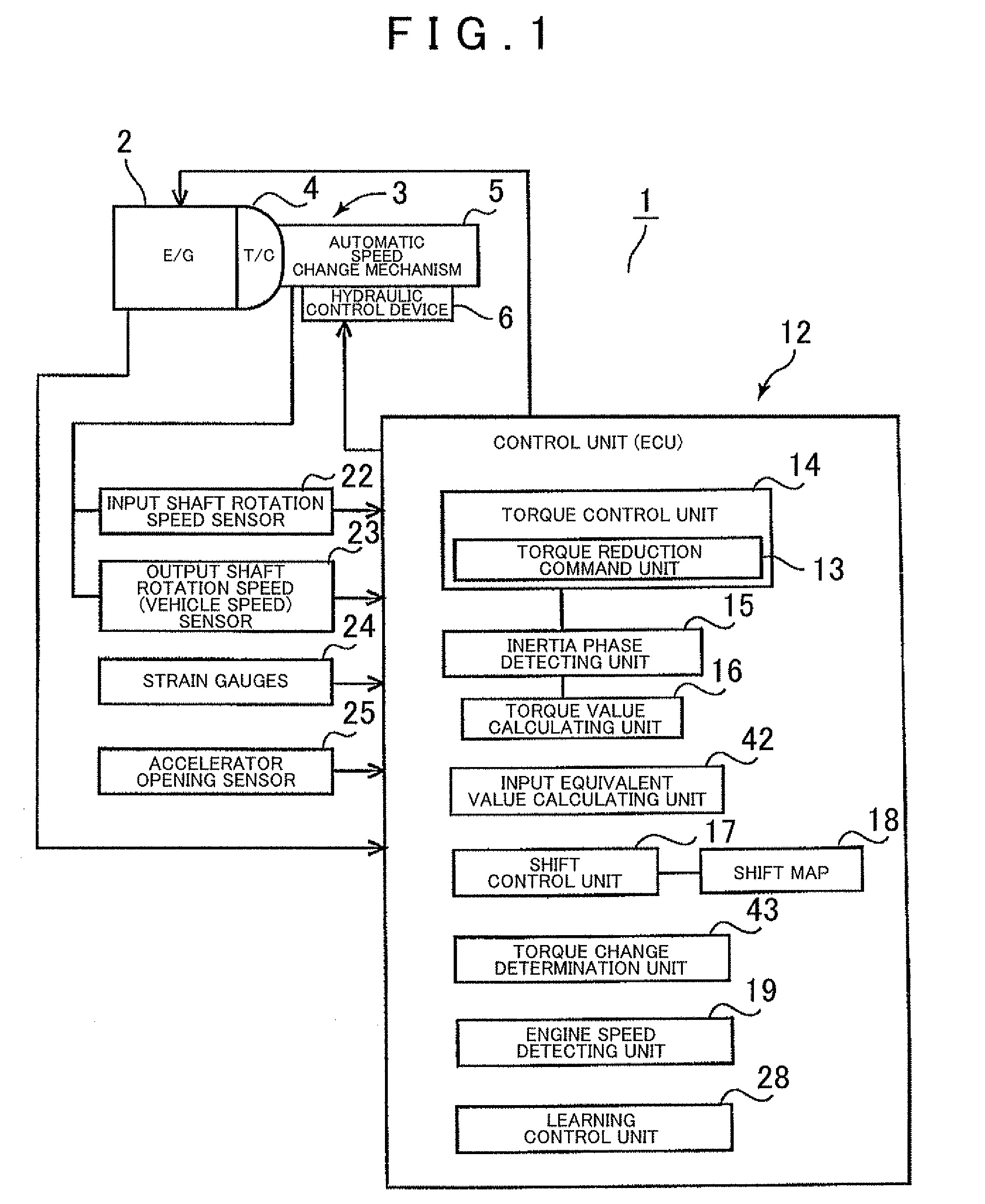
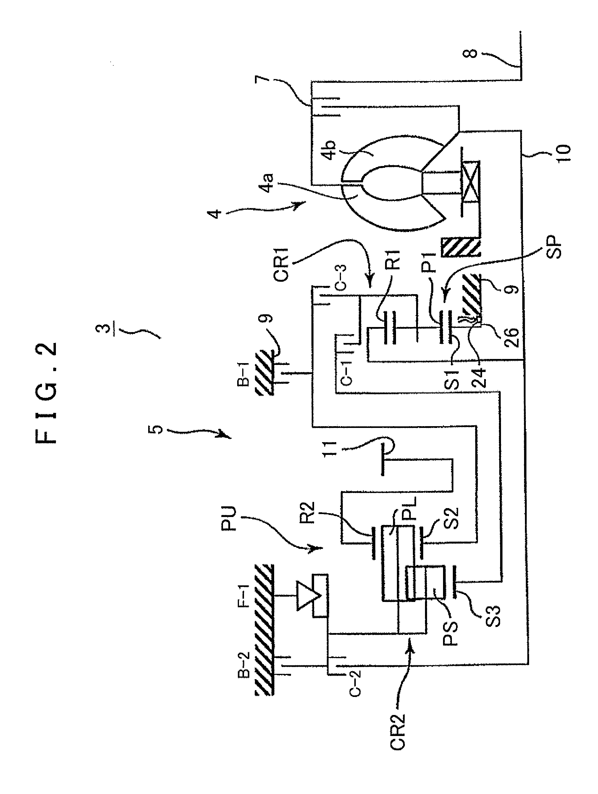
[0028]First, the structure of an automatic transmission 3 to which the present invention can be applied will be described with reference to FIG. 2. FIG. 2 shows an automatic transmission 3 that is suitable for use in, for example, an FF (front engine, front drive) type vehicle. The automatic transmission 3 has an input shaft 8 connected to an engine 2 (refer to FIG. 1) serving as a driving source, and is provided with a torque converter 4 and an automatic speed change mechanism 5 with the centers thereof aligned along the axis of the input shaft 8. A reference a transmission case 9 houses the automatic speed change mechanism 5.

[0029]The automatic transmission 3 is a stepped automatic transmission that has clutches C-1, C-2, and C-3, and brakes B-1 and B-2 serving as friction engagement elements whose engagement states determine which one of a plurality of power transmissi...


PUM


Abstract

Strain gauges and a torque value calculating unit detect a value for torque acting on a sun gear based on a reaction force, an input equivalent value calculating unit calculates an input torque equivalent value based on the torque value detected, a torque reduction command unit issues a command to the engine for changing torque, and a torque change determination unit determines, based on the input torque equivalent value calculated, whether or not the torque of the engine has been appropriately changed in accordance with the command. Consequently, based on the torque value measured for the sun gear that is a component of the automatic speed change mechanism, it can be precisely determined whether or not the torque change for the engine has been appropriately achieved as targeted.

Description

INCORPORATION BY REFERENCE[0001]The disclosure of Japanese Patent Application No. 2008-085342 filed on Mar. 28, 2008, including the specification, drawings and abstract is incorporated herein by reference in its entirety.BACKGROUND OF THE INVENTION[0002]1. Field of the Invention[0003]The present invention relates to a shift control apparatus for an automatic transmission mounted on a vehicle such as an automobile, and particularly to a shift control apparatus for an automatic transmission that is capable of precisely determining whether or not a torque change that has been applied to a driving source such as an engine is that targeted.[0004]2. Description of the Related Art[0005]Automatic transmissions in general, particularly stepped automatic transmissions, shift by switching engagement among friction engagement elements (clutches and / or brakes), with hydraulic shift control, using linear solenoid valves and so forth. Hydraulic pressures are supplied to hydraulic servos for the fr...

Claims


Application Information

Patent Timeline
Patent Type & Authority Applications(United States)
IPC IPC(8): G06F19/00B60W10/04B60W10/06B60W10/10B60W10/11B60W10/115B60W30/19B60W40/00B60W50/06F16H59/16F16H59/68F16H61/04F16H61/68F16H61/684F16H61/686F16H63/40F16H63/50
CPCB60W10/115B60W30/19F16H59/16B60Y2400/307F16H63/502F16H2061/0087F16H61/686
Inventor KUBO, TAKAYUKI
Owner AISIN AW CO LTD
Why Eureka
Try Eureka