Statistical timing analyzer and statistical timing analysis method

a technology of statistic timing analysis and analyzer, which is applied in the field of statistic timing analyzer and statistical timing analysis method, can solve the problems of large delay variation in semiconductor integrated circuits, caused by variations, and the time required to execute static timing analysis becomes considerably long

Inactive Publication Date: 2009-10-01
KK TOSHIBA
View PDF7 Cites 8 Cited by
  • Summary
  • Abstract
  • Description
  • Claims
  • Application Information

AI Technical Summary

Problems solved by technology

With recent downsizing of the semiconductor integrated circuit, the delay variation in the semiconductor integrated circuit, caused by variations in the process conditions or operation environments, has become great.
However, in the method of treating the delay variation as corners, time required to execute the static timing analysis becomes considerably long when the number of variation factors becomes large.
Therefore, when the number of variation factors is n, 2n times of the static timing analysis need to be performed by the number of all paths, and consequently this method is impractical when there are many variation factors.
Therefore, the analysis time is short when the subset of the circuit extracted by the first static timing analysis is small, while the analysis time is adversely long when the subset of the circuit extracted by the first static timing analysis is large.
A common circuit usually has more than thousands of critical paths, and the method disclosed in U.S. Pat. No. 7,181,713 does not enable to perform the static timing analysis for such a circuit in a sufficiently short analysis time.
In the method disclosed in Japanese Patent Application Laid-open No. 2005-92885, however, the variation factor treated as a range cannot be considered throughout the range, and therefore the analysis accuracy is deteriorated.
Therefore, an analysis of a condition in which the voltage and the temperature both have the maximum values is not achieved by the statistical static timing analysis.

Method used


Image

  • Statistical timing analyzer and statistical timing analysis method
  • Statistical timing analyzer and statistical timing analysis method
  • Statistical timing analyzer and statistical timing analysis method

Examples


first embodiment

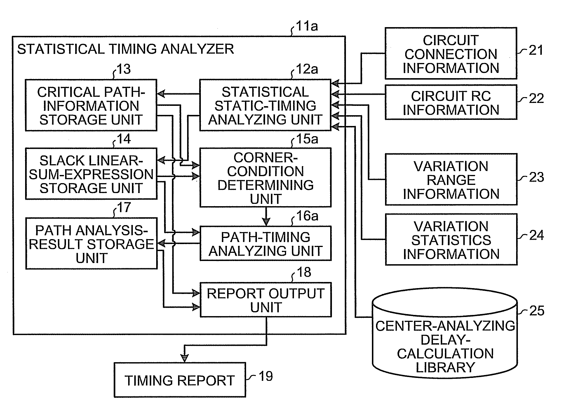
[0032]FIG. 1 is a block diagram of a general configuration of a statistical timing analyzer according to the present invention.

[0033]With reference to FIG. 1, a statistical timing analyzer 11a includes a statistical static-timing analyzing unit 12a, a critical path-information storage unit 13, a slack linear-sum-expression storage unit 14, a corner-condition determining unit 15a, a path-timing analyzing unit 16a, a path analysis-result storage unit 17, and a report output unit 18.

[0034]The statistical static-timing analyzing unit 12a calculates a linear sum expression of slacks as a statistical slack for which n (n is an integer equal to or larger than 2) variation factors are statistically considered, based on a statistical static timing analysis of a semiconductor integrated circuit. The critical path-information storage unit 13 stores therein information of a critical path selected by the statistical static-timing analyzing unit 12a. The slack linear-sum-expression storage unit 1...

second embodiment

[0059]FIG. 4 is a block diagram of a general configuration of a statistical timing analyzer according to the present invention.

[0060]With reference to FIG. 4, a statistical timing analyzer 11b includes a path-timing analyzing unit 16b, instead of the path-timing analyzing unit 16a in FIG. 1. The path-timing analyzing unit 16b can obtain a delay value of an element from a corner-analyzing delay-calculation library 26 while the path-timing analyzing unit 16a in FIG. 1 obtains the delay value of the element from the center-analyzing delay-calculation library 25. The corner-analyzing delay-calculation library 26 is a set of delay calculation libraries including all combinations of best and worst conditions with respect to the variation factors X1, X2, . . . , Xm treated as a range. For example, when there are three variation factors treated as a range, the corner-analyzing delay-calculation library 26 is a set of delay calculation libraries in eight (=23) conditions.

[0061]FIG. 5 is a bl...

third embodiment

[0075]FIG. 8 is a block diagram of a general configuration of a statistical timing analyzer according to the present invention.

[0076]With reference to FIG. 8, a statistical timing analyzer 11c includes a path-timing analyzing unit 16c, instead of the path-timing analyzing unit 16b shown in FIG. 4, and additionally includes a corner-by-corner path counter 31, a corner-by-corner path-number storage unit 32, an overall-circuit-timing analyzing unit 34, and an overall-circuit analysis-result storage unit 35.

[0077]The corner-by-corner path counter 31 counts the number of paths in each of the corner conditions determined by the corner-condition determining unit 15a. The corner-by-corner path-number storage unit 32 stores therein the number of paths in each corner condition, counted by the corner-by-corner path counter 31. The overall-circuit-timing analyzing unit 34 performs the timing analysis of the overall circuit to be analyzed. The overall-circuit analysis-result storage unit 35 stor...


PUM


Abstract

A statistical timing analyzer comprises a statistical static-timing analyzing unit that performs a statistical static timing analysis of a semiconductor integrated circuit; a corner-condition determining unit that determines corner conditions of the semiconductor integrated circuit based on a result of the statistical static timing analysis; and a path-timing analyzing unit that performs a static timing analysis of the semiconductor integrated circuit based on the corner conditions.

Description

CROSS-REFERENCE TO RELATED APPLICATIONS[0001]This application is based upon and claims the benefit of priority from the prior Japanese Patent Application No. 2008-093253, filed on Mar. 31, 2008; the entire contents of which are incorporated herein by reference.BACKGROUND OF THE INVENTION[0002]1. Field of the Invention[0003]The present invention relates to a statistical timing analyzer and a statistical timing analysis method, and, more particularly to a statistical timing analyzer and a statistical timing analysis method that are suitable for application to a method of analyzing delay variations in a semiconductor integrated circuit, caused by variations in process conditions or operation environments.[0004]2. Description of the Related Art[0005]With recent downsizing of the semiconductor integrated circuit, the delay variation in the semiconductor integrated circuit, caused by variations in the process conditions or operation environments, has become great. To ensure the operation ...

Claims


Application Information

Patent Timeline
Patent Type & Authority Applications(United States)
IPC IPC(8): G06F17/50
CPCG06F17/5031G06F30/3312
Inventor YODA, TOMOYUKI
Owner KK TOSHIBA
Why Eureka
Try Eureka