Portable Panel Construction and Method for Making the Same
Active Publication Date: 2009-10-08
PS FURNITURE
63 Cites 18 Cited by
AI-Extracted Technical Summary
Problems solved by technology
These patents use less than ideal methods to construct the substantially planar surfaces and connect these surfaces.
Both of these conventional methods result in either very heavy panels that are difficult to transport or panels susceptible to water damage.
Both of these methods are labor intensive, while the show surfaces, or show skins, of these panels are susceptible to glue failure rendering these panels disfigured and/or unusable.
These include the susceptibility of the...
Method used
[0076]The first and second skins 24 and 26, which can also be first and second laminate skins, are attached to the polyurethane layers before the polyurethane layers dry. This creates a strong bond between the skins and the polyurethane layers to increase the durability and attachment thereto. Additionally the impregnation of the polyurethane layers through the fiber layers increases the strength and bonding of the polyurethane layers and skin to the fiber layers and a core upon which they are attached. Prior to application of the polyurethane the fiber layers 16 and 18 are attached to the core 12. For example, staples, glue or other fastening systems known in the art to attach fiber layers to a core layer can be used.
[0078]The first and second skins 24 and 26 can comprise sound attenuating or sound absorbing material. For example one or both of the skins 24 and 26 could include sound attenuating material. In a preferred embodiment, the second skin 26 covers the bottom portion of a table and comprises fabric, such as cloth. This type of second skin can deaden sound and is less likely to abrasively engage something sliding under the table, such as the clothing or body parts of a person sitting, or seated, at the table. This selection of the sound attenuating material can provide a noticeable sound difference in a room filled with such tables.
[0079]The first and second skins 24 and 26 can comprise a metal portion that extends substantially the width 11 and length 13. This laminate/metal skin composite can be placed over the wet polyurethane and fiberglass as described above. This laminate/metal skin composite helps to prevent warping caused by expansion and retraction of the laminate that is associated with changing environmental conditions. For example, the inward forces on a 48 inch by 48 inch panel were calculated to be 10,000 lbs when the laminate dries out. The metal skin can prevent the laminate from moving and prevent warping of the panel 10.
[0082]The frame 34 is designed with panel gaps 35 spaced to accept the core. The fiber layers, polyurethane layers and skins are all placed over the frame on the external surfaces 52 and 54 to increase the bonding and engagement between the frame pieces 34. The external surfaces opposite 52 and 54 also get a fiber layer, polyurethane, and a skin.
[0083]The locking element 48 preferably includes a rotatable hook 56 that engages the extrusion of the female side or part 36. Fasteners such as screws 58 can hold in the hook or lock 56. This hook further facilitates the engagement between adjacent panels 32 during on-site assembly of the portable floor 30 and their disengagement upon disassembly of the floor after use. To engage the extrusion the hook 56 is rotated, for example using a known device such as an Allen wrench, inserted into hole 57. Correspondingly, the female side 36 includes engaging aperture 41 into which the locking element 48 engages to secure adjacent panels 32.
[0086]As illustrated in FIGS. 15-17, multiple teeth 31 can extend inwardly from the sides, or projections 33, of the channel 35 to engage the core 12. The projections can include stabilizers 37, also extending inwardly, to engage the core 12. The core can include a perimeter section 19 that includes a reduced thickness. The reduced thickness can be positioned in the channel 35 and the projections 33 can be forced, or compressed, inwardly. The compression of the projections 33 inward can further reduce a neck portion 21 of the perimeter section 19. The teeth 31 can extend into the neck portion 21 and engage the perimeter section 19 at the neck portion 21. This can result in a reduced thickness of the channel 35, corresponding generally to the location of the teeth 31, as compared to the rest of the...
Benefits of technology
[0031]Yet another object of the present invention is to provide a panel and/or portable table that have the ability to be stacked flat so as to take up less space when not in use and still maintain a desired l...
Abstract
Disclosed herein is a portable panel having numerous favorable characteristics. The panel comprises a core having a length, a width, a first side and a second side. A first fiber layer is attached to the first side while a second fiber layer is attached to the second side. A first polyurethane layer is impregnated in the first fiber layer while a second polyurethane layer is impregnated into the second fiber layer. A first skin is attached to the first polyurethane layer while a second skin is attached to the second polyurethane layer. The panel can be used in the manufacture of tables, flooring, risers, stages, bleachers, and the like.
Application Domain
Construction materialStruts +10
Technology Topic
Fiber layerEngineering +2
Image
Examples
- Experimental program(1)
Example
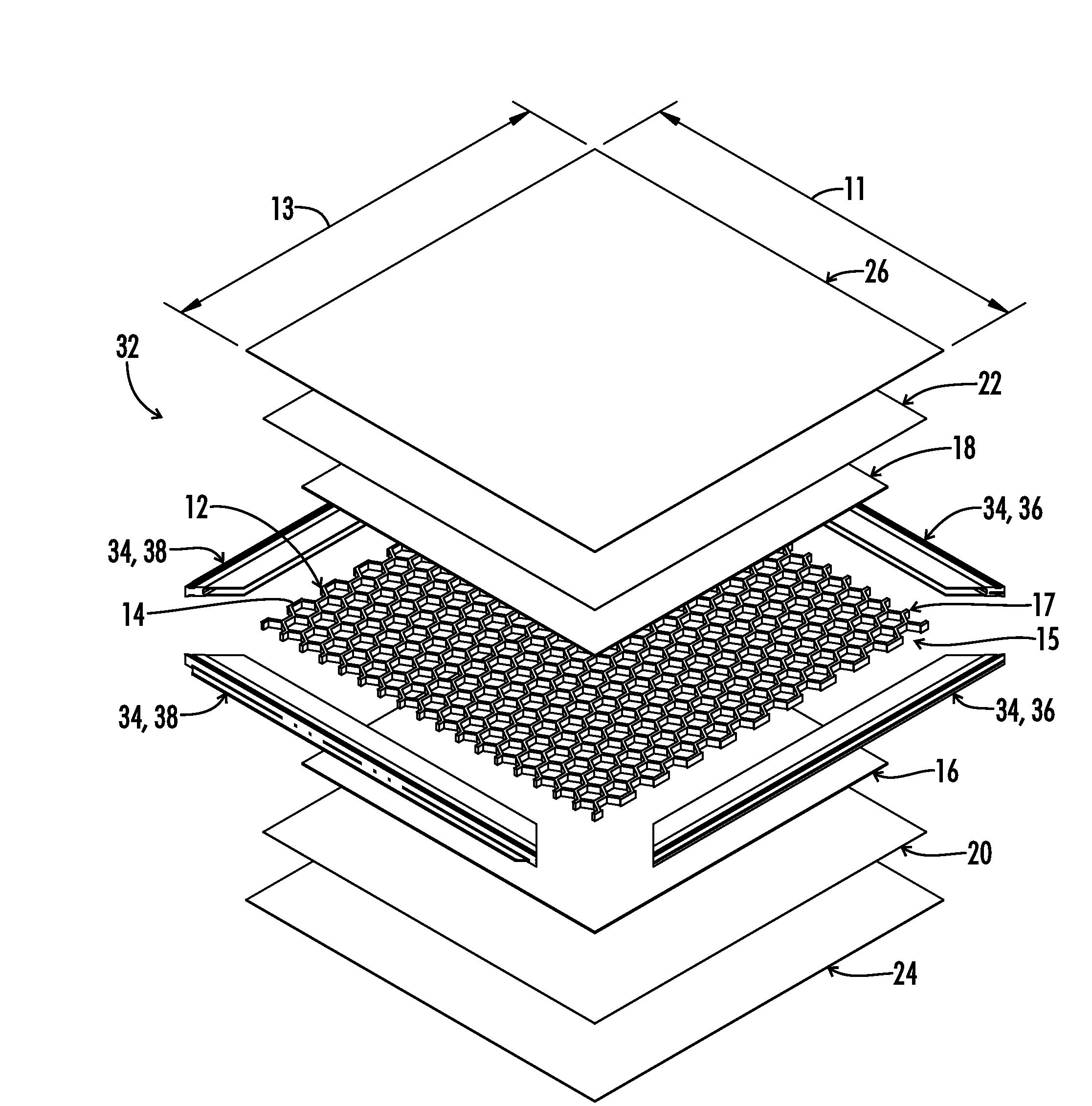
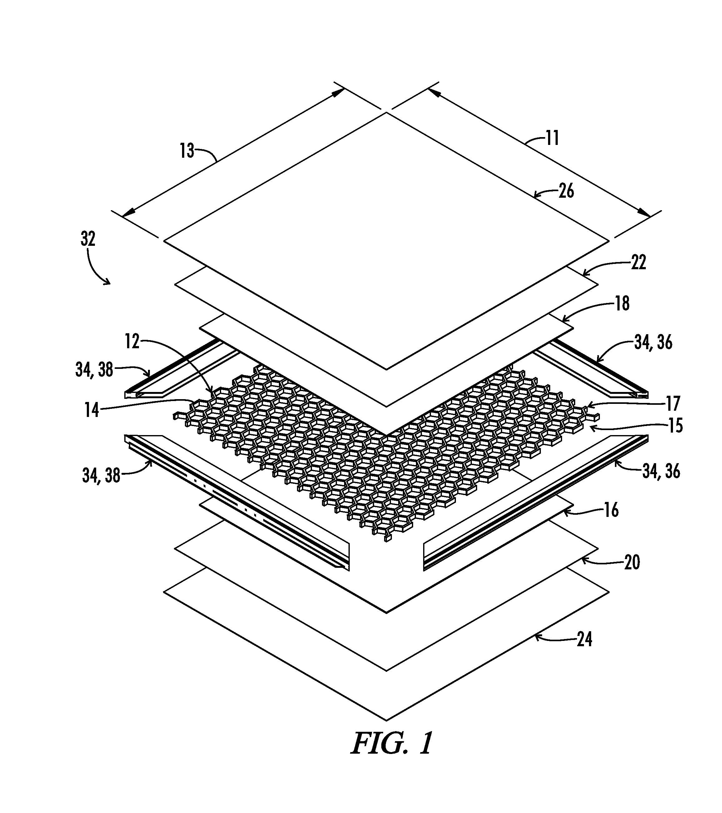
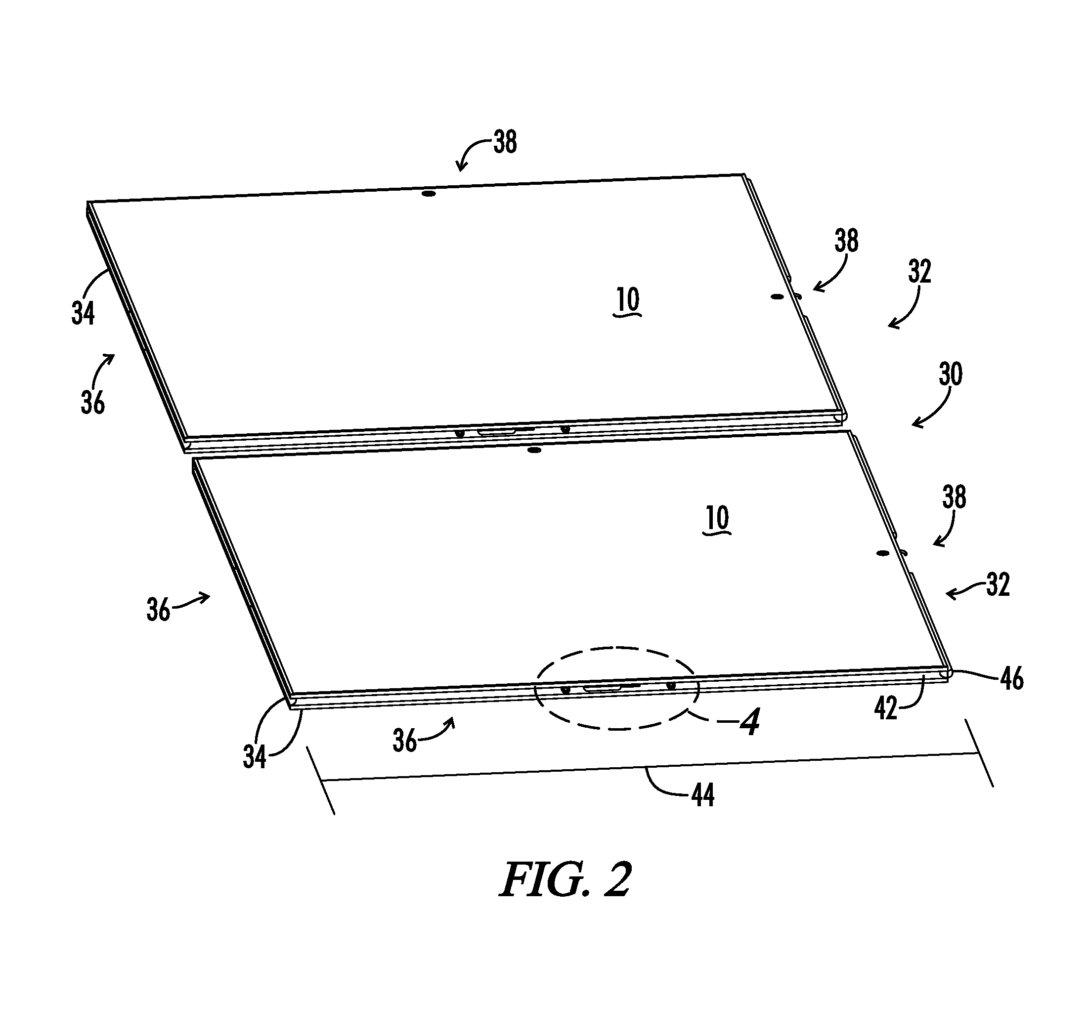
[0073]Referring generally to FIGS. 1-22C, a panel is shown and generally designated by the numeral 10. The panel 10 has many uses and can be used in conjunction with a portable floor, as seen in FIGS. 1-12, a portable table, as shown in FIGS. 13, 14 and 18-22C, risers, bleachers event staging, walls, and the like.
[0074]The panel 10 will have a core 12. The core can be made from many materials including paper honeycomb, plastic honeycomb, polyurethane, EPS, wood, metal, and the like. The core can preferably include a plurality of openings 14 wherein the openings are substantially uniformly spaced along the width 11 and length 13 of the core. The openings 14 can be honeycomb in shape as best seen in FIGS. 1 and 13.
[0075]First and second fiber layers 16 and 18 are attached to the first and second sides 15 and 17 of the core 12. First and second polyurethane layers 20 and 22 impregnate first and second fiber layers 16 and 18 respectively. First and second skins 24 and 26 are attached to the first and second polyurethane layers 20 and 22, respectively.
[0076]The first and second skins 24 and 26, which can also be first and second laminate skins, are attached to the polyurethane layers before the polyurethane layers dry. This creates a strong bond between the skins and the polyurethane layers to increase the durability and attachment thereto. Additionally the impregnation of the polyurethane layers through the fiber layers increases the strength and bonding of the polyurethane layers and skin to the fiber layers and a core upon which they are attached. Prior to application of the polyurethane the fiber layers 16 and 18 are attached to the core 12. For example, staples, glue or other fastening systems known in the art to attach fiber layers to a core layer can be used.
[0077]Panels constructed in accordance with this disclosure have many benefits including exhibiting a light weight and a high strength for a given cross section, especially in view of prior art panels. The current inventive panels also include an option for the addition of strengthening ribs and/or edges to the design. Additionally an integral column mount or leg support structure can be mounted within the lightweight core. Many surface finishes are possible including, but not limited to leather, laminate, vinyl, spray polyurethane, wood grain, texture and color variances, such as the use of various paints. Additionally various patterns and/or designs can be incorporated into the skins 24 and 26. These variances can be realized through the type of skin 24 and 26 that is bonded in with the polyurethane layers 20 and 22 around the fiber layers 16 and 18 and a core 12. Additionally an ultraviolet protective coating can be added if desired. Panels so constructed are also water resistant and have an increased durability for a wide range of uses.
[0078]The first and second skins 24 and 26 can comprise sound attenuating or sound absorbing material. For example one or both of the skins 24 and 26 could include sound attenuating material. In a preferred embodiment, the second skin 26 covers the bottom portion of a table and comprises fabric, such as cloth. This type of second skin can deaden sound and is less likely to abrasively engage something sliding under the table, such as the clothing or body parts of a person sitting, or seated, at the table. This selection of the sound attenuating material can provide a noticeable sound difference in a room filled with such tables.
[0079]The first and second skins 24 and 26 can comprise a metal portion that extends substantially the width 11 and length 13. This laminate/metal skin composite can be placed over the wet polyurethane and fiberglass as described above. This laminate/metal skin composite helps to prevent warping caused by expansion and retraction of the laminate that is associated with changing environmental conditions. For example, the inward forces on a 48 inch by 48 inch panel were calculated to be 10,000 lbs when the laminate dries out. The metal skin can prevent the laminate from moving and prevent warping of the panel 10.
[0080]One example of an item in which an inventive panel can be used is in the production of a portable floor. The portable floor 30 includes a plurality of floor panels 32 that include the core 12, fiber layers 16 and 18, polyurethane layers 20 and 22, and skins 24 and 26 as previously discussed. Additionally, each panel includes a frame 34 surrounding the core 12. The frame 34 preferably includes two (2) female sides 36 and two (2) male sides 38. The female side 36 includes a lock engaging section 41, and a channel 42 having a channel length 44 substantially equal to the core length 13. The female side 36 is extruded such that it can directly engage the protrusion 46. The male side 38 includes the protrusion 46 shaped to engage the channel 42 and a locking element 48. The protrusion 46 has a protrusion length 50 substantially equal to the channel length 44.
[0081]In a preferred embodiment the frame is composed of metal, such as aluminum, but can also be constructed of polymers. The protrusion 46 of one of the panels 32 is positioned to engage the channel 42 of an adjacent panel 32 to restrict movement of the panels in relation to one another. The engagement between the protrusion 46 and channel 42 preferably restricts both rotational and vertical movement of the panels in relation to one another. This can best be illustrated by FIG. 7 and FIGS. 2-3 showing engaged and disengaged embodiments of the male and female sides 36 and 38 of the frame 34.
[0082]The frame 34 is designed with panel gaps 35 spaced to accept the core. The fiber layers, polyurethane layers and skins are all placed over the frame on the external surfaces 52 and 54 to increase the bonding and engagement between the frame pieces 34. The external surfaces opposite 52 and 54 also get a fiber layer, polyurethane, and a skin.
[0083]The locking element 48 preferably includes a rotatable hook 56 that engages the extrusion of the female side or part 36. Fasteners such as screws 58 can hold in the hook or lock 56. This hook further facilitates the engagement between adjacent panels 32 during on-site assembly of the portable floor 30 and their disengagement upon disassembly of the floor after use. To engage the extrusion the hook 56 is rotated, for example using a known device such as an Allen wrench, inserted into hole 57. Correspondingly, the female side 36 includes engaging aperture 41 into which the locking element 48 engages to secure adjacent panels 32.
[0084]The floor panels 32 can also be constructed to include an alignment/lateral movement suppression system. The system comprises a gap in the protrusion 46 where the locking element 56 is located. This gap is used as a guide to mate to two pegs 62, which can be cap head screws, located in the female side 36. As such, corresponding floor panels 32 are aligned to establish a portable floor 30 that will be secure.
[0085]The extrusion incorporates at least one tooth 31 running the length of the extrusion on both sides of the channel 35. This tooth 31 is compressed so as to bite into the core to secure the frame to the core.
[0086]As illustrated in FIGS. 15-17, multiple teeth 31 can extend inwardly from the sides, or projections 33, of the channel 35 to engage the core 12. The projections can include stabilizers 37, also extending inwardly, to engage the core 12. The core can include a perimeter section 19 that includes a reduced thickness. The reduced thickness can be positioned in the channel 35 and the projections 33 can be forced, or compressed, inwardly. The compression of the projections 33 inward can further reduce a neck portion 21 of the perimeter section 19. The teeth 31 can extend into the neck portion 21 and engage the perimeter section 19 at the neck portion 21. This can result in a reduced thickness of the channel 35, corresponding generally to the location of the teeth 31, as compared to the rest of the channel 35. This facilitates the hold between the frame 34 and the core 12.
[0087]The engagement of the frame 34 to the core 12, through both the teeth 31 and the various layers and skins, and the engagement of the portions of the frame to each other for a given panel 10 provides an excellent resistance to deformation, including deformation by warping. This encapsulated frame, or extrusion, is designed strongly enough to overcome the bowing forces caused by expansion and retraction of the laminate and the adhesion is strong enough to maintain the integrity of the various layers.
[0088]Another example of a device incorporating one of the current inventive panels is a portable table 64. The portable table 64 includes support legs 66 and a planar surface 68 attached to the support legs 66. The planar surface 68 includes one of the panels 10 and a top exterior skin 70 and bottom exterior skin 72. The top skin 70 and bottom skin 72 can be specifically designed for use as a table and can include corresponding edges 74 and 76 that engage and can be sealed together.
[0089]The table 64 can also include support structures 78 that are substantially equal to the core length 13. The support structures 78 can provide additional rigidity to the table 64. Additional support structures, such as flat steel stock, 80 can be positioned in the core 12 between the polyurethane layers 20 and 22. These supports can be used to attach the hardware from the legs 66 to the planar surface 68.
[0090]The bottom skin 72 can have recessed areas 73 positioned to accept the support structure 78. This can also provide a handle area by which to carry the tables 64. The table 64 can be made in both circular and polygonal shapes, such as rectangular, square and the like. Alternately, the legs 66 can be attached to the planar surface 68 or table top 68 by metal inserts that are integral to the bottom skin 72.
[0091]As seen in FIGS. 19B-E, the table 64 can include recessions 75 that facilitate storage of the support legs 66 when the table 64 is not in use. The recession can “hide” the legs 66 to facilitate stacking of the tables. The legs 66 can still be visible, but the legs 66 can be positioned in a manner that allows the tables 64 to be stacked, for example 10-20 high. For example, the bottom side of the table 64 can be indented or crushed to accept the legs 66. More specifically, the bottom side of the core 12 can be indented making an impression where the legs 66 will fit when the table 64 is stacked and maintain the bottom of the table 64 substantially flat. The legs 66 can fit into the bottom of the table to result in a substantially coplanar arrangement with the planar surface of the table when folded. Alternately described, the legs and table can be substantially flush when the legs are folded into the table.
[0092]Additionally, a table that uses a column support rather than folding legs, such as a cocktail table, can be made according to the current disclosure. For such a table, the planar surface 68 with core 12 can be constructed generally as described above. As seen in FIGS. 22A-C, a column connection 94 can be placed integral to the core 12 of the planar surface 68 during the construction process. The column support 94 is shaped to accept the column 96 and removably secure the column 96 within the column support 94. This can be accomplished numerous ways, including an interference fit between the column 96 and the column support 94, threads on the column 96 operating with threads in the opening 95 of the column support 94, push button connections, ball and seat, tongue and grove connections, etc.
[0093]During the curing process the fiber layers 16 and 18 and polyurethane layers 20 and 22 harden to form a solid surface around the core 12 and column connection 94. The column connection 94 can then become a solid integral part of the core 12 and planar surface 68 and allow flush exterior surfaces. This is in contrast to typical prior art tables that have the connection for a column support protruding from the exterior surface of the table. The inventive connection allows the tables to be securely and compactly stacked.
[0094]As best seen in FIGS. 18A-21C, the table 64 includes a contoured edge 80 that cooperates with a frame, such as a cap 82, to provide a durable, yet light weight perimeter for the table 64. The contoured edge 80, which can be described as a pinched edge 80, is preferably formed as part of the perimeter of the core 12, fiber layers 16 and 18, and polyurethane layers 20 and 22. The contoured edge 80 includes a reduced thickness portion 84 that is smaller than the combined thickness of the core 12, fiber layers 16 and 18, and polyurethane layers 20 and 22. An intermediate thickness portion 86 extends from the reduced thickness portion 84 opposite the body portion of the core 12. The contoured edge 80 can be described as having a neck and a head extending from the neck. Alternate shapes are possible for the contoured edge 80 with an important characteristic being the facilitation of the mechanical attachment between the core and the cap 82. For example, a cross-section of the contoured edge 80 can generally look “T-shaped”, as shown in the figures.
[0095]The cap 82 can include a concave shape designed to accept and hold the contoured edge 80. The cap can include projections 90 having extensions 92, or teeth 92, that can collectively form the concave shape. The cap 82 can include a rounded top 88 and is preferably composed of cast urethane material, but alternate suitable materials can be used. Skins 24 and 26 can be applied as previously discussed, but preferably before the addition of the cap 82 to the table 64.
[0096]The perimeter for the table 64 can be formed by using a press that will form the pinched edge 80 by squeezing the composite material, comprised of the core 12, fiber layers 16 and 18, and polyurethane layers 20 and 22, together. When the press closes, impressions from protrusions in the two halves of the press are forced into the composite material around the perimeter of the core. The resulting pinched edge 80 becomes a solid shape around the perimeter and provides a mechanical lock for the cap 82. Additionally, the cap 82 can be glued to the pinched edge core 80 for a reinforced attachment.
[0097]The combination of the pinched edge core 80 and the cap 82 provides improved impact resistance for the corners and edges of the table 64. The resulting perimeter of the table 64 is solid, impact resistant to repeated drops, smooth, aesthetically pleasing, and connected to the panel portion of the table 64 in a way that it will not peel away.
[0098]Since the fiber layers 16 and 18 and polyurethane layers 20 and 22 harden to form a solid surface around the contoured edge 80, forces against the cap 82 are deflected and absorbed. Typical prior art composite honeycomb panels do not have a perimeter, or edge, designed for severe impact and have only a wrap around edge. The core of those prior art composite honeycomb panels are typically made of paper, aluminum or polypropylene and in of themselves do not provide any impact resistance. Nor do the skins of those prior art tables provide any impact resistance. Other manufacturers of composite panels rely on the edge material itself for impact resistance. Initial test on the inventive contoured edge 80 and cap 82 design confirmed that a panel made with this process can withstand impact drops. For example, tests showed that an inventive panel when dropped on its edge withstood over seven (7) direct corner impacts from a twenty-four (24) inch high drop without failure with a panel weighing under fifty pounds (in the test the panel weighed 42 pounds). This is a huge advantage over any other panels using a honeycomb type core.
[0099]Another benefit of the inventive contoured edge 80 and cap 82 design is in the manufacturing process itself. Previously, when a cast urethane edge was poured around panels made with a straight honeycomb edge, a seal, such as tape, had be placed all around the perimeter to avoid any openings where air could be entrained into the cast urethane, thus weakening the cast urethane. Also, typically honeycomb panel edges are inconsistent. As such, previously when there were openings or uneven surface edges on the honeycomb panels, excess urethane was used, and wasted, or the machine shot time was off and scrap material was produced. This increased the manufacturing time and cost of making a honeycomb panel with a urethane edge. With the inventive pinched edge 80, the tape process is generally eliminated and a consistent molded edge is realized.
[0100]Thus, although there have been described particular embodiments of the present invention of a new and useful New Portable Panel Construction and Method for Making the Same, it is not intended that such references be construed as limitations upon the scope of this invention except as set forth in the following claims.
PUM
Property | Measurement | Unit |
Length | ||
Thickness | ||
Polarity |
Description & Claims & Application Information
We can also present the details of the Description, Claims and Application information to help users get a comprehensive understanding of the technical details of the patent, such as background art, summary of invention, brief description of drawings, description of embodiments, and other original content. On the other hand, users can also determine the specific scope of protection of the technology through the list of claims; as well as understand the changes in the life cycle of the technology with the presentation of the patent timeline. Login to view more.
Similar technology patents
Conveying device for conveying workpieces
Owner:GROB WERKE & K G
Semiconductor package and fabrication method thereof
Owner:SILICONWARE PRECISION IND CO LTD
User interface for searching referenced information
Owner:NAVIGATE SURGICAL TECH
Camera module having chamfer, photosensitive assembly, preparation method, and electronic device
Owner:NINGBO SUNNY OPOTECH CO LTD
Classification and recommendation of technical efficacy words
- less space
- level of stability
Isotope production system and cyclotron having a magnet yoke with a pump acceptance cavity
Owner:GENERAL ELECTRIC CO
Flexible ignitor assembly for air/fuel mixture and method of construction thereof
Owner:FEDERAL MOGUL IGNITION
Method and Apparatus For Testing AFCI Device for Series ARC Detection
Owner:SIEMENS IND INC
Folding deck mechanism
Owner:MTD PRODUCTS
Portable Table Construction and Method for Making the same.
Owner:PS FURNITURE
Dust-free horizontal optical fiber fusion device
PendingCN110554461Alevel of stability
Owner:内蒙古鸿信电力股份有限公司