Electronic musical instrument

US20090249943A1Active Publication Date: 2009-10-08ROLAND CORP

Image

  • Electronic musical instrument
  • Electronic musical instrument
  • Electronic musical instrument

Examples


Embodiment Construction

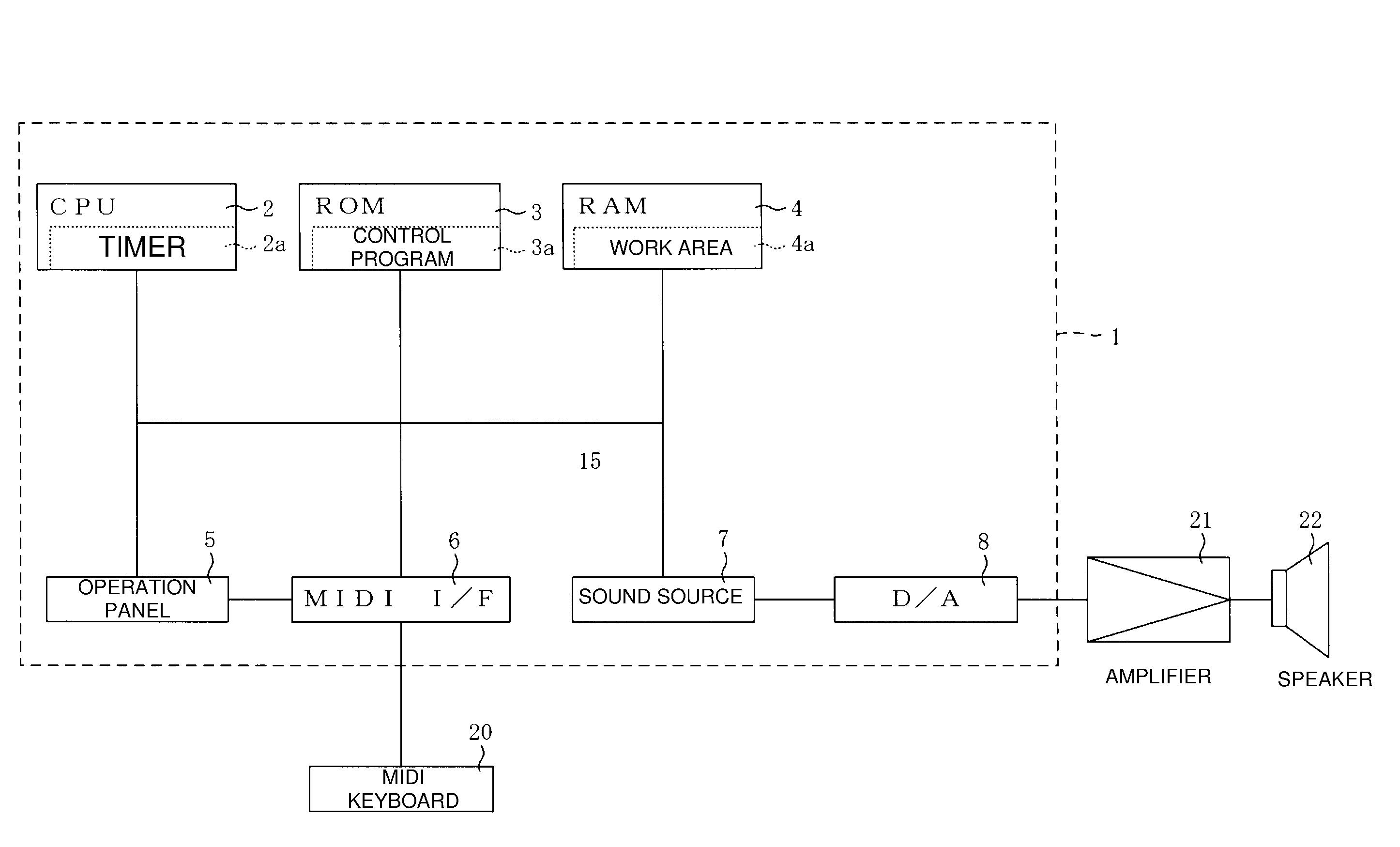
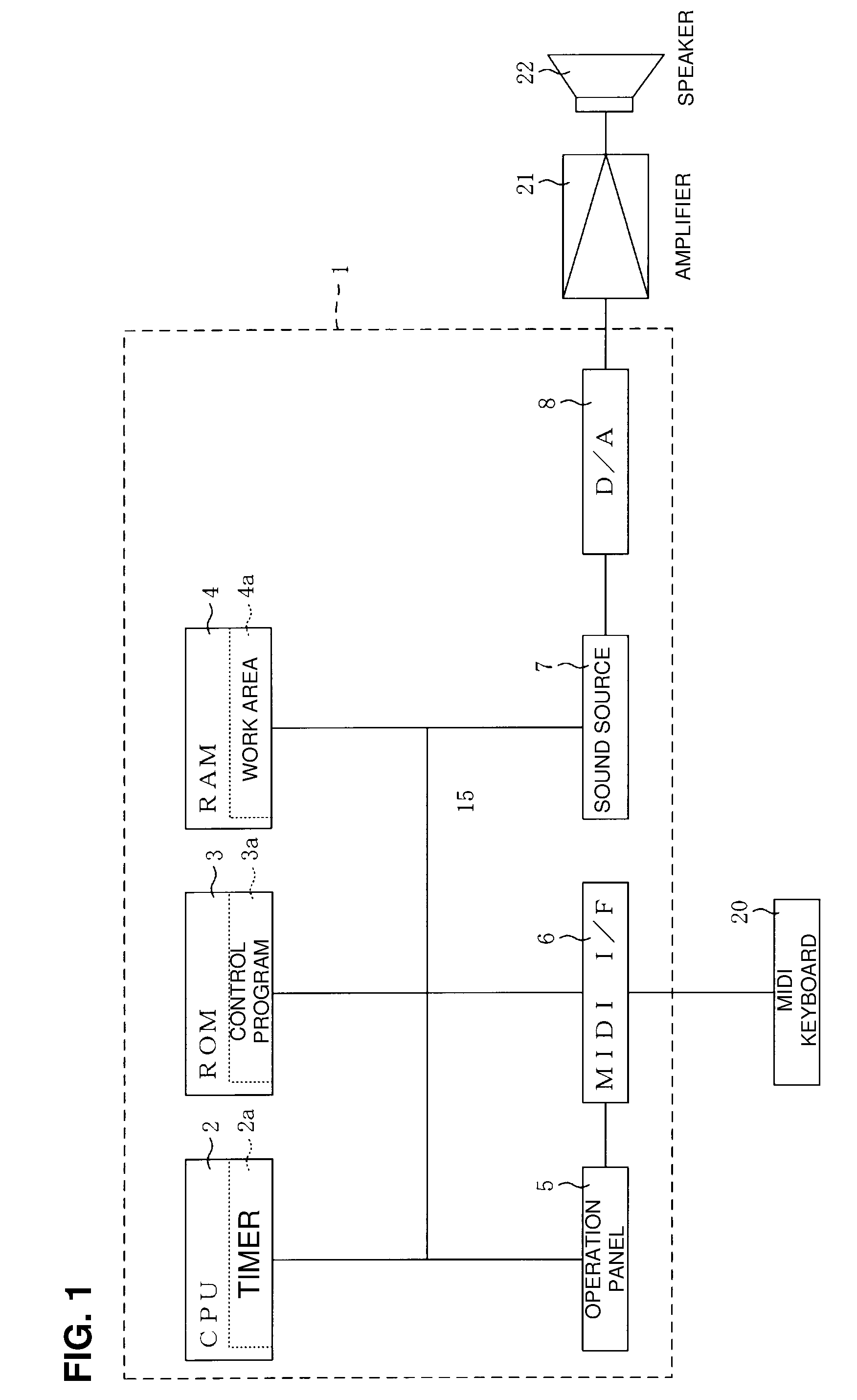
[0026]Preferred embodiments of the invention are described below with reference to the accompanying drawings. FIG. 1 is a block diagram of the electrical structure of an electronic musical instrument 1 in accordance with an embodiment of the invention. The electronic musical instrument 1 is capable of generating musical sounds that suit performance operations by, for example, a keyboard.

[0027]As shown in FIG. 1, the electronic musical instrument 1 is primarily provided with a CPU 2, a ROM 3, a RAM 4, an operation panel 5, a MIDI interface 6, a sound source 7, and a D / A converter 8. The CPU 2, the ROM 3, the RAM 4, the operation panel 5, the MIDI interface 6 and the sound source 7 are mutually connected through a bus line.

[0028]The CPU 2 controls each of the sections of the electronic musical instrument 1 according to fixed value data and control programs stored in the ROM 3 and RAM 4. The CPU 2 includes a timer 2a wherein the timer 2a counts clock signals, thereby measuring time. By...


PUM


Abstract

An electronic musical instrument includes: an input device that inputs a sound generation instruction that instructs to start generating a musical sound and a stop instruction that instructs to stop the musical sound being generated by the sound generation instruction; a sound source that starts generation of a musical sound in response to the sound generation instruction, and stops generation of the musical sound in response to the stop instruction; an on-on time timer device that measures a time difference between a first sound generation instruction inputted by the input device and a second sound generation instruction inputted next to the first sound generation instruction; a gate time timer device that measures a time difference between the second sound generation instruction and a stop instruction that instructs to stop a musical sound generated in response to the second sound generation instruction; an attack characteristic setting device that sets an attack characteristic of the musical sound generated in response to the second sound generation instruction to have a shorter attack time as the time difference measured by the on-on time timer device becomes shorter; a release characteristic setting device that sets a release characteristic of the musical sound generated in response to the second sound generation instruction to have a shorter release time as the time difference measured by the gate time timer device becomes shorter; and an instruction device that instructs the sound source to start generation of a musical sound with an attack characteristic set by the attack characteristic setting device in response to an input of the second sound generation instruction by the input device, and instructs the sound source to stop generation of a musical sound with a release characteristic set by the release characteristic setting device in response to an input of the stop instruction by the input device.

Description

CROSS-REFERENCE TO RELATED FOREIGN APPLICATION[0001]This application is a non-provisional application that claims priority benefits 5 under Title 35, Unites States Code, Section 119(a)-(d) from Japanese Patent Application entitled “ELECTRONIC MUSICAL INSTRUMENT” by Ikuo Tanaka and Taro Umemoto, having Japanese Patent Application Serial No. JP2008-098953, filed on Apr. 7, 2008, which application is incorporated herein by reference in its entirety.BACKGROUND[0002]1. Technical Field[0003]Embodiments of the present invention generally relate to electronic musical instruments, and more particularly, to electronic musical instruments capable of applying to musical sounds specified envelopes that suit each musical performance method.[0004]2. Related Art[0005]Electronic musical instruments that change an envelope of a musical sound to be generated according to a performance method are known. Japanese Laid-open Patent Application 2002-32083 (Patent Document 1) describes an electronic musical...

Claims


Application Information

Patent Timeline
08 Oct 2009
Publication
US20090249943A1
IPC
G10H7/02
CPC
G10H1/057
Inventors
TANAKA, IKUO; UMEMOTO, TARO