Techniques for producing an electrical pulse

Inactive Publication Date: 2009-10-08
CORRELATED MAGNETICS RES LLC
View PDF24 Cites 41 Cited by
  • Summary
  • Abstract
  • Description
  • Claims
  • Application Information

AI Technical Summary

Problems solved by technology

As the above process is inefficient in many respects, there is an ongoing need to improve upon existing techniques to produce an electrical pulse.

Method used


Image

  • Techniques for producing an electrical pulse
  • Techniques for producing an electrical pulse
  • Techniques for producing an electrical pulse

Examples


Embodiment Construction

[0061]The present invention will now be described more fully in detail with reference to the accompanying drawings, in which the preferred embodiments of the invention are shown. This invention should not, however, be construed as limited to the embodiments set forth herein; rather, they are provided so that this disclosure will be thorough and complete and will fully convey the scope of the invention to those skilled in the art. Like numbers refer to like elements throughout.

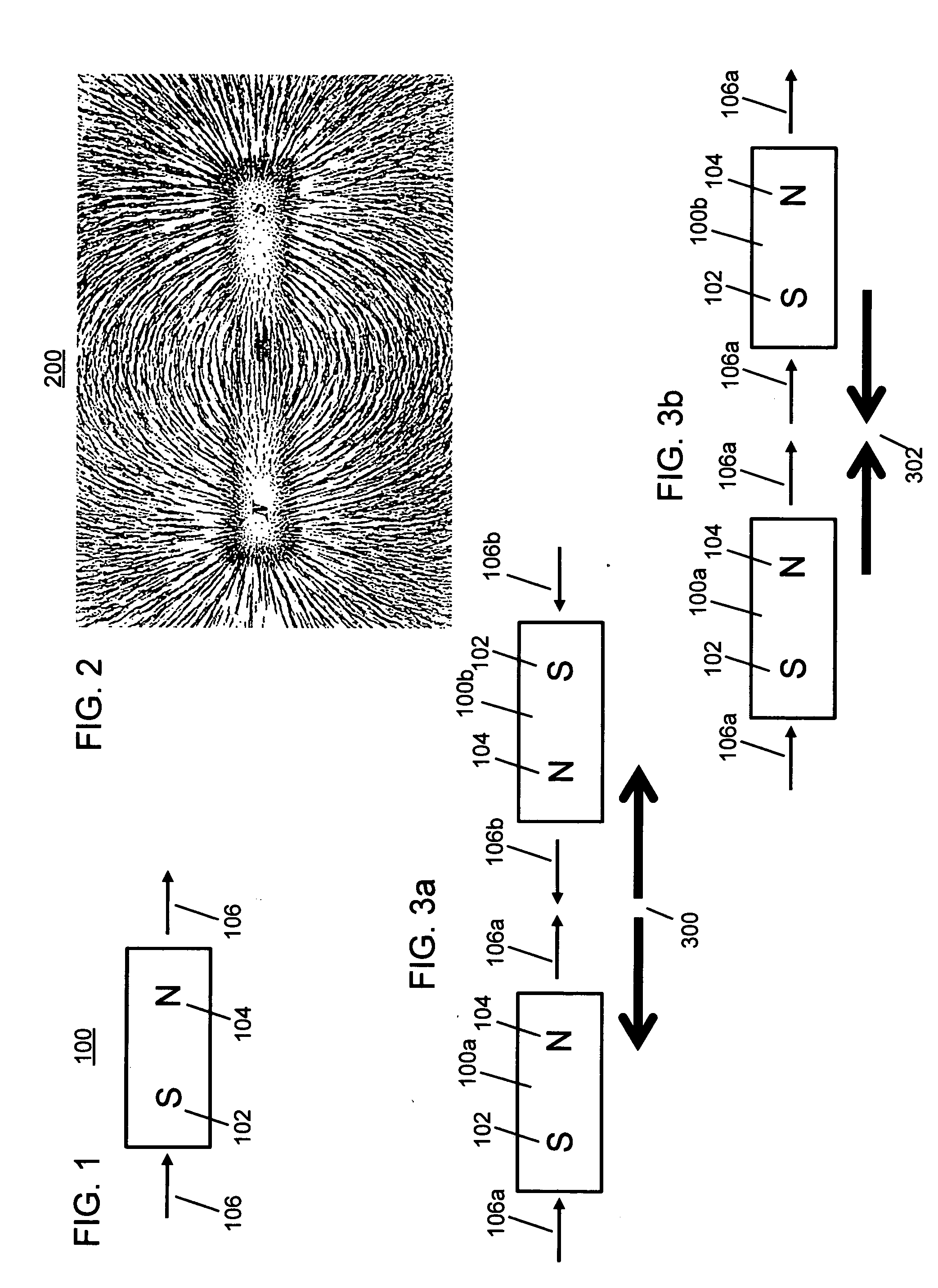
[0062]FIG. 1 depicts South and North poles and magnetic field vectors of an exemplary magnet. Referring to FIG. 1, a magnet 100 has a South pole 102 and a North pole 104. Also depicted are magnetic field vectors 106 that represent the direction and magnitude of the magnet's moment. North and South poles are also referred to herein as positive (+) and negative (−) poles, respectively. In accordance with the invention, magnets can be permanent magnets, impermanent magnets, electromagnets, electro-permanent magnet...


PUM


Abstract

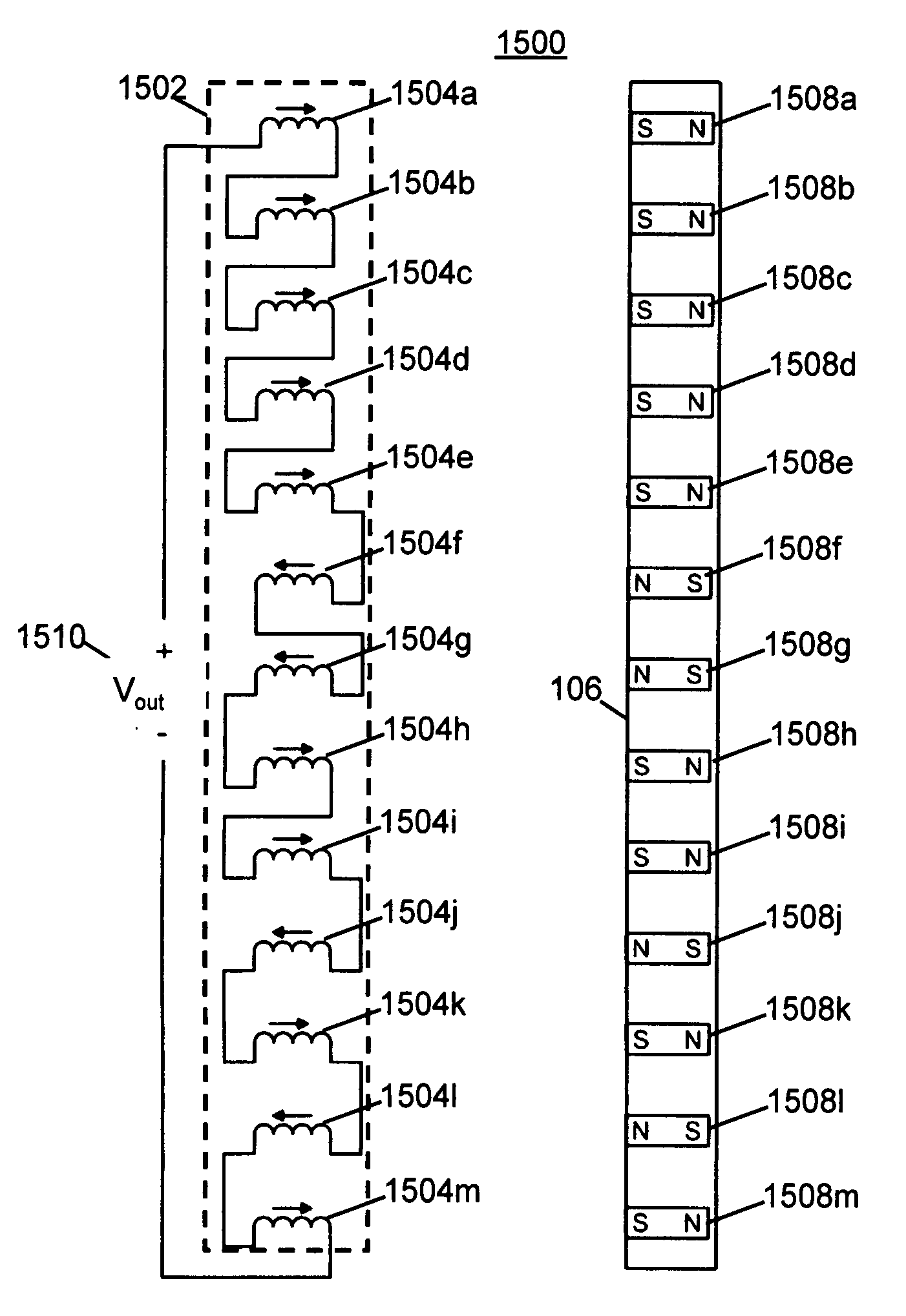
Embodiments of the present invention provide an apparatus, comprising a field emission source having polarities and positions in accordance with a code, a plurality of connected coils adapted to move proximate to said field emission source and having positions in accordance with said code, and wherein an electrical pulse is created when said field emission source is aligned with said plurality of connected coils according to said code.

Description

CROSS-REFERENCE TO RELATED APPLICATIONS[0001]This Non-provisional application is a continuation-in-part of Non-provisional application Ser. No. 12 / 358,423, filed Jan. 23, 2008, titled “A Field Emission System and Method”, by Fullerton et al., which is a continuation-in-part of Non-provisional application Ser. No. 12 / 123,718, filed May 20, 2008, titled “A Field Emission System and Method”, which claims the benefit of U.S. Provisional Application Ser. No. 61 / 123,019, filed Apr. 4, 2008, titled “A Field Emission System and Method”, which are all incorporated by reference herein in their entirety.BACKGROUND OF THE INVENTION[0002]The creation of an electric pulse is vital to numerous applications. Several methods are currently available to produce such a pulse and are in need of improvement. For example, but not by way of limitation, a magneto is a device used in the ignition system of gasoline-powered internal combustion engines to provide pulses of high voltage electrical power to the ...

Claims


Application Information

Patent Timeline
Patent Type & Authority Applications(United States)
IPC IPC(8): F02P23/00H02K39/00G01B7/14
CPCF02P3/02F02P23/00H02K21/22H03K2017/9706H03K3/45H03K17/97H02K39/00
Inventor FULLERTON, LARRY W.ROBERTS, MARK D.
Owner CORRELATED MAGNETICS RES LLC
Why Eureka
Try Eureka