Phase Change Fluid Spring and Method for Use of Same

a fluid spring and phase change technology, applied in the field of fluid springs, can solve the problems of high pressure at the surface, commercially unreasonable or impractical to charge the fluid springs to these pressures at the surface, and the safety risk of operating personnel is very substantial,

Inactive Publication Date: 2009-10-08
HALLIBURTON ENERGY SERVICES INC
View PDF37 Cites 93 Cited by
  • Summary
  • Abstract
  • Description
  • Claims
  • Application Information

AI Technical Summary

Benefits of technology

[0008]The present invention disclosed herein comprises phase change fluid spring operable for use with a downhole tool such as an annulus pressure responsive downhole testing tool. The phase change fluid spring containing a phase change fluid that is chargeable at the surface to significantly lower pressures while providing higher pressures downhole

Problems solved by technology

Use of such high pressures at the surface presents a very substantial safety risk to operating personnel during the charging and handling of these fluid springs.
Moreover, i

Method used


Image

  • Phase Change Fluid Spring and Method for Use of Same
  • Phase Change Fluid Spring and Method for Use of Same
  • Phase Change Fluid Spring and Method for Use of Same

Examples


example 1

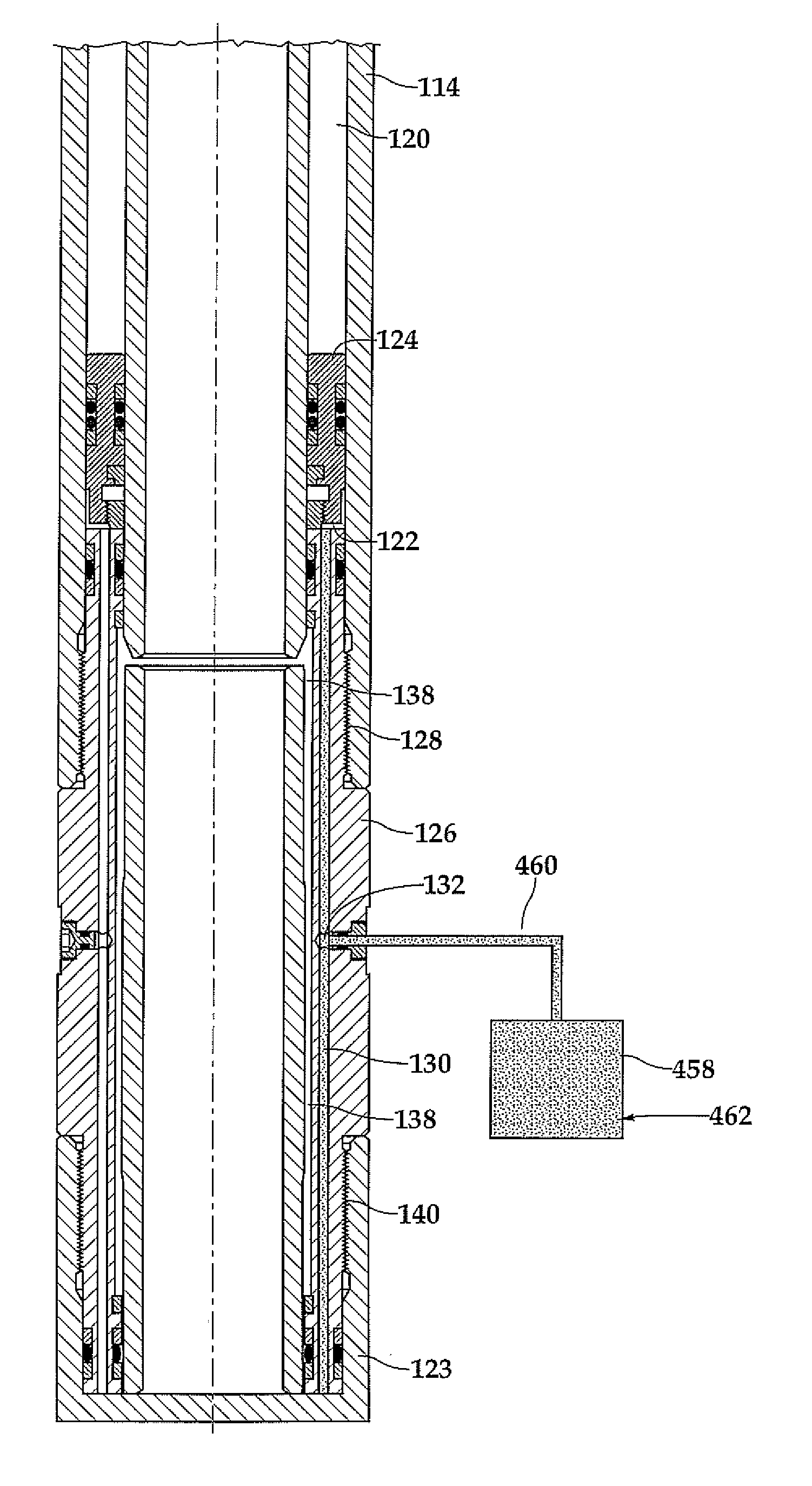
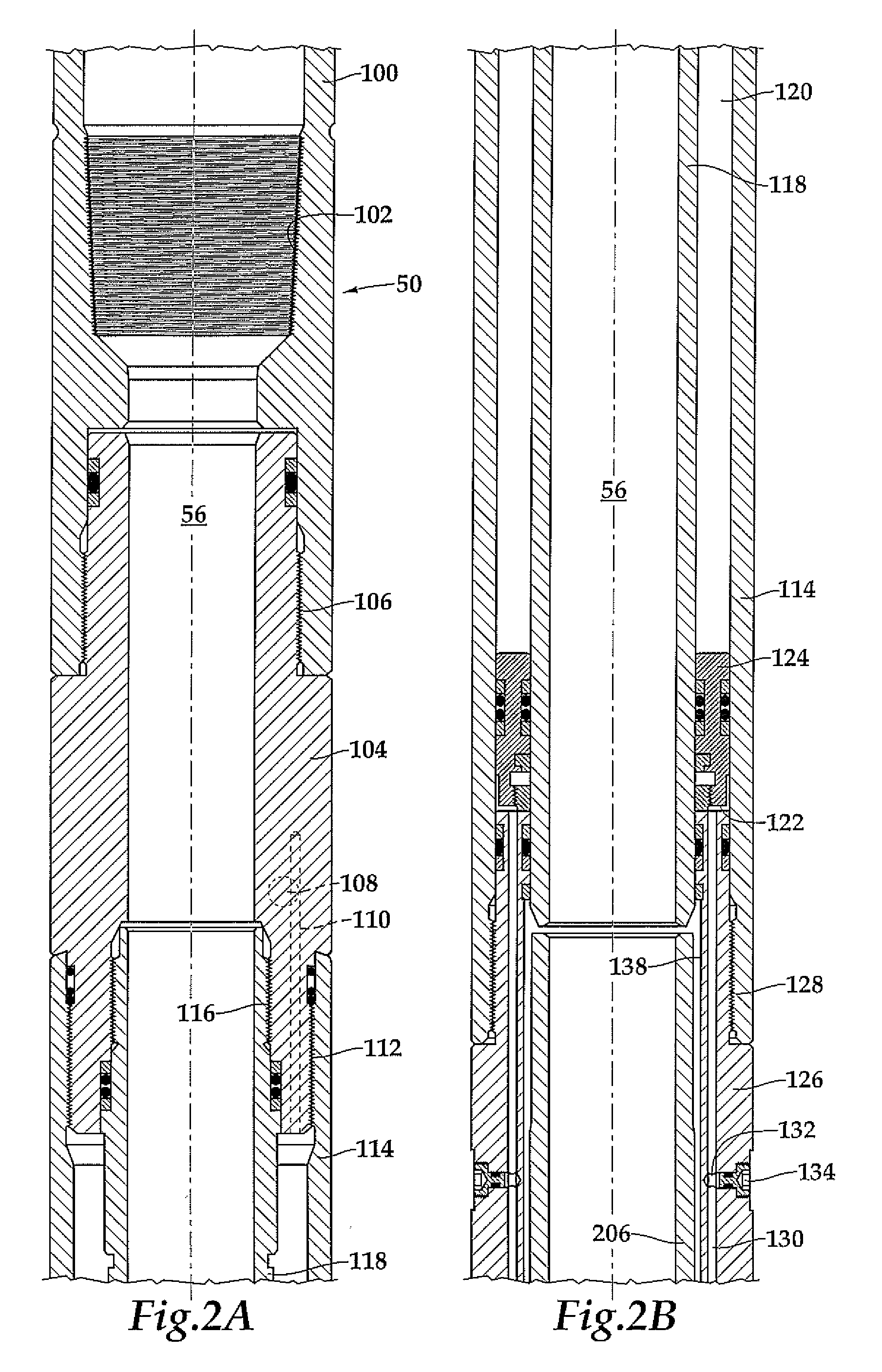
[0089]It is determined that a testing tool with phase change fluid spring 50 will be used in a particular downhole environment using a phase change fluid of carbon dioxide. The hydrostatic pressure in the annulus may be determined by the weight and / or density of the mud and the depth of the mud at which the testing toot with phase change fluid spring 50 will be used. For example, if it is determined that the hydrostatic pressure in the unpressurized annulus is approximately 10,000 psi, then the phase change fluid in the pressurized gas chamber 120 should sufficiently exceed the hydrostatic such as a pressure of at least 10,500 psi pressure. As described above, energy is stored in the phase change fluid spring 450 by compressing the phase change fluid by pressurizing the annulus using the pump 24 via the control conduit 26. In this example, the amount of phase change fluid to be charged into chamber 120 at the surface can be determined based upon the required downhole volume using th...

example 2

[0093]The desired downhole volume (V) of the phase change fluid, in this case carbon dioxide is 16 liters. The hydrostatic pressure at the desired depth is approximately 20,000 psi. The downhole temperature at the desired depth is approximately 250° C. or 523.15 K. The ideal gas law, PV=nRT, may be used to determines the required liquid volume of carbon dioxide at the surface. Using the gas constant of R=0.0821 liter·atmosphere·mole−1·K−1, it can be determined that approximately 253.49 moles of carbon dioxide are required. Charging the chamber 120 at the surface at a temperature of about 88° F. will require a pressure of at least 1,070 psi and preferably 1,500 psi to maintain the carbon dioxide in a liquid state. Liquid carbon dioxide has a density of approximately 1.03 gms / ml, thus 253.49 moles of liquid carbon dioxide, which has a molecular mass of 44.0095, will weight approximately 11,155 gms. Using the density of liquid carbon dioxide, this weight of carbon dioxide will occupy a...

example 3

[0094]In another example, the amount of phase change fluid that is charged into the phase change fluid spring 450 may determined by weight. For example, the change in weight of the phase change fluid source 454 or the phase change fluid spring 450 may be monitored to determine if the required amount of phase change fluid has been charged into the chamber 120.


PUM


Abstract

A phase change fluid spring (450) for actuating a downhole tool (50) in a wellbore. The phase change fluid spring (450) includes a housing (114) defining a fluid chamber (120) and a phase change fluid disposed within the fluid chamber (120). The phase change fluid is in a first phase and at a first pressure at the surface. The phase change fluid is in a second phase and at a second pressure in the wellbore, the second pressure being greater than the first pressure. The phase change fluid is operable to store and release energy downhole to actuate the downhole tool (50).

Description

TECHNICAL FIELD OF THE INVENTION[0001]This invention relates, in general, to a fluid spring operable to store and release energy downhole and, in particular, to a phase change fluid spring that contains a fluid that transitions from a liquid phase at a first pressure on the surface to a gas or supercritical phase at a second, higher pressure downhole.BACKGROUND OF THE INVENTION[0002]Without limiting the scope of the present invention, its background is described with reference to the operation of annulus pressure responsive downhole tools, as an example.[0003]In oil and gas wells, it is common to conduct well testing and stimulation operations to determine production potential and enhance that potential. Annulus pressure responsive downhole tools have been developed which operate responsive to pressure changes in the annulus between the testing string and the wellbore casing that can sample formation fluids for testing or circulate fluids therethrough. These tools typically incorpor...

Claims


Application Information

Patent Timeline
IPC IPC(8): E21B34/08
CPCE21B23/04E21B34/14
Inventor WRIGHT, ADAM D.NORMAN, LEWISSCHULTZ, ROGER L.
Owner HALLIBURTON ENERGY SERVICES INC
Why Eureka
Try Eureka