
Sectional back reamer for horizontal directional drilling

a back reamer and directional drilling technology, applied in mechanical equipment, shaft equipment, sewer pipelines, etc., can solve the problems of serious injury, death, and serious injury of installers, and achieve the effect of improving safety for operators, reducing the size and weight of components, and quick and easy assembly and disassembly

Active Publication Date: 2009-10-08
DIMITROFF TED R
View PDF8 Cites 14 Cited by
  • Summary
  • Abstract
  • Description
  • Claims
  • Application Information

AI Technical Summary

Benefits of technology

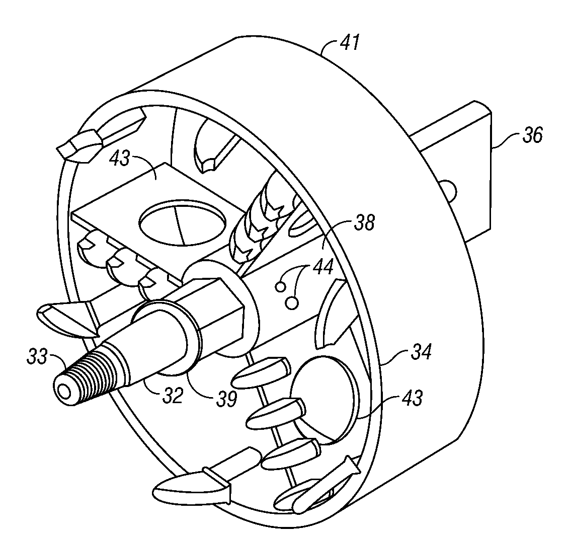
[0019]The sectional back reamer of the present invention is intended for use in horizontal directional drilling, and comprises three components which can be assembled and disassembled quick and easily by an operator at each end of the drilling operation. The reamer includes a main shaft connectable to the drill string or pipe, a reamer or cutting head mountable on the main shaft, and a pull tab mountable to the reamer. The connections between the main shaft and the reamer cutting head, and between the cutting head and the pull tab include faceted surfaces to preclude rotation of the components relative to one another. The components are assembled sequentially by the installer in the trench or on top of the ground. The smaller size and weight of the components, as compared to the prior art one-piece back reamers, simplifies and greatly improves the safety to the operator driving the attachment and detachment of the reamer's components to and from the drill pipe.

Problems solved by technology

However, trenching can be time consuming and can cause substantial damage to existing structures or roadways.
This manual operation is dangerous, since the person typically stands in front of or straddles over the top of the reamer in order to install the reamer on the drill string.
Communication errors are known to occur, with a resulting premature actuation of the back reamer while the installer is still preparing the reamer, thus causing serious injury, and even death, to the installer.
The heavy weight of the reamer also results in back problems for the installer, both during attachment of the reamer and detachment of the reamer after the utility hole is formed.
Furthermore, attachment and detachment of the reamer normally requires the use of large and heavy wrenches, which also may cause injuries if the wrenches are dropped or slipped.

Method used


Image

  • Sectional back reamer for horizontal directional drilling
  • Sectional back reamer for horizontal directional drilling
  • Sectional back reamer for horizontal directional drilling

Examples


Embodiment Construction

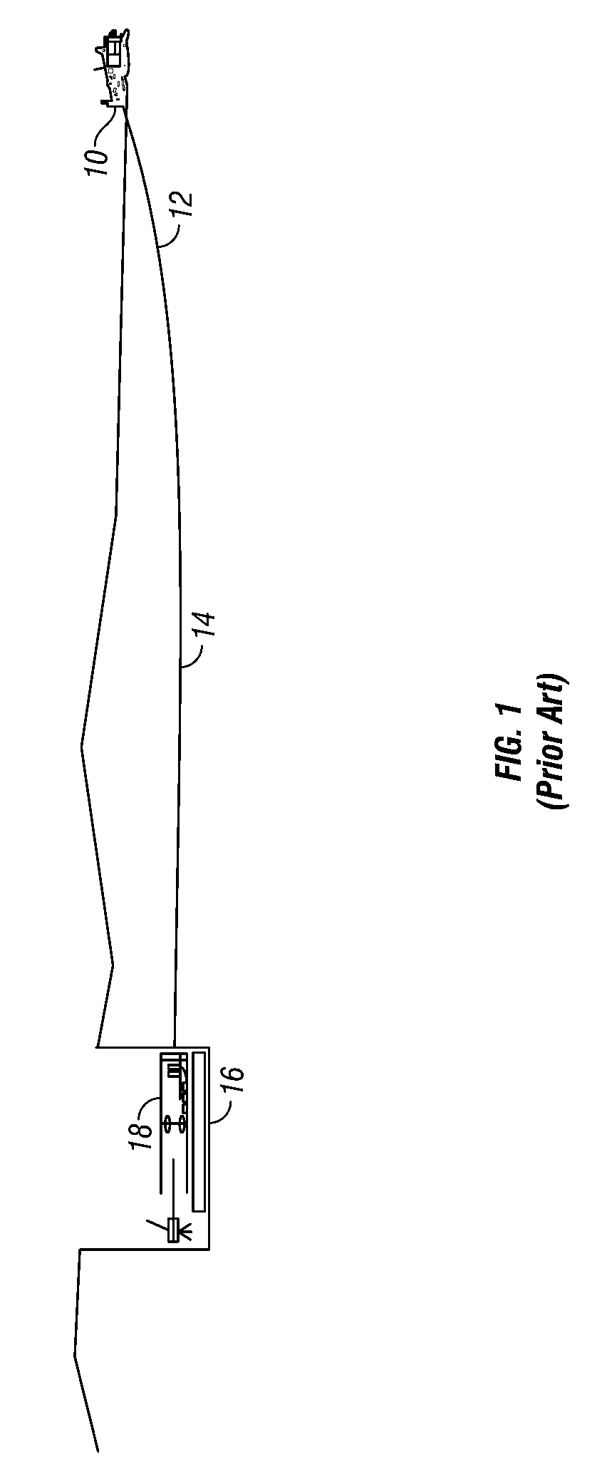
[0029]FIG. 1 shows a conventional horizontal directional drilling machine 10 having a drill string or pipe 12 to form a pilot hole 14 extending to a trench 16. The back reamer 18 is attached to the forward end of the drill string 12 in the trench and then pulled backwardly through the pilot hole 14 to enlarge the hole.

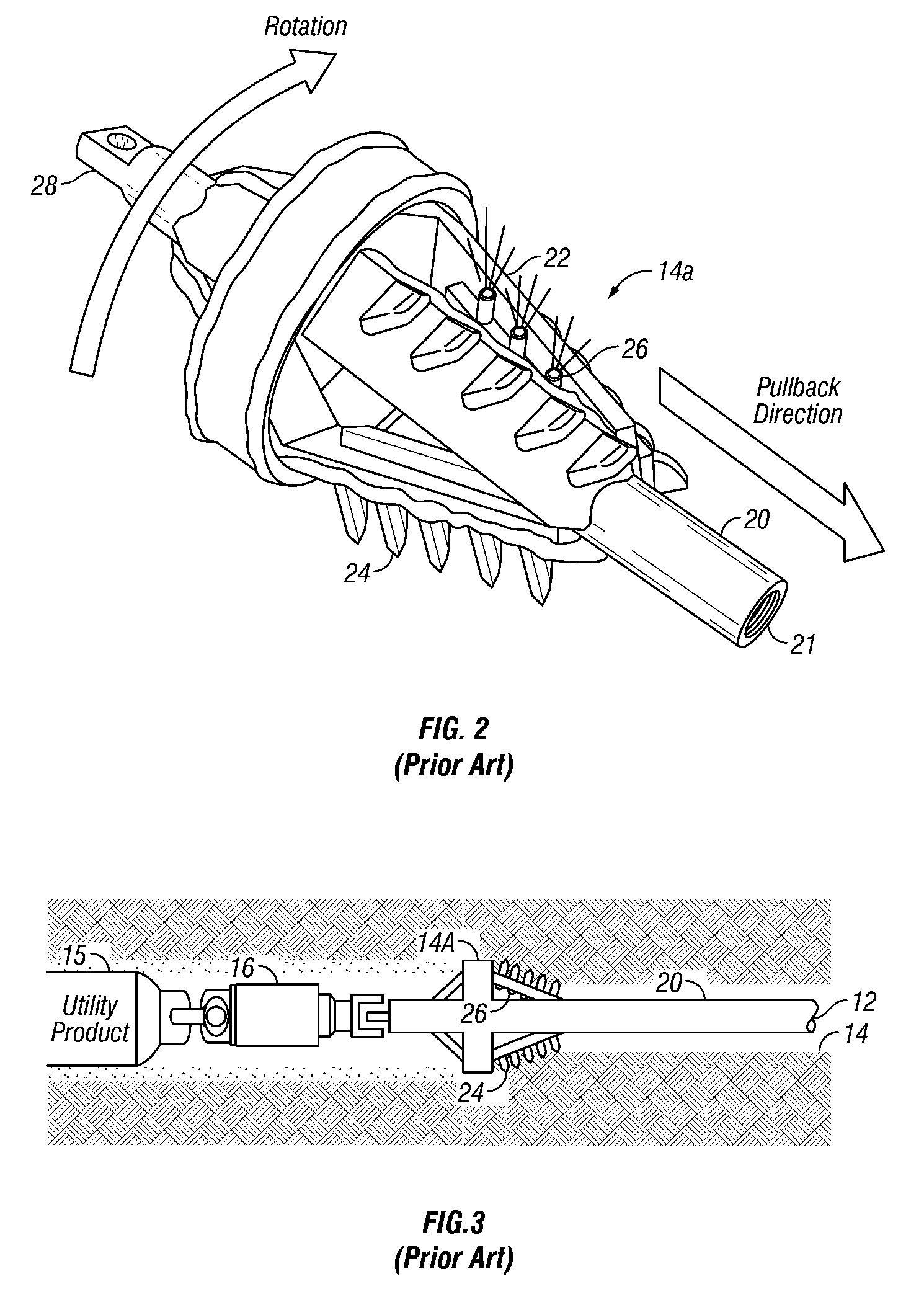
[0030]Two conventional configurations of back reamers 14A and 14B are shown in FIGS. 2 and 4. As seen in FIGS. 3 and 5, a utility product 15 is attached to the reamer 14A, 14B via a swivel coupling 16 so as to be pulled through the enlarged hole as the reamer 14A, 14B is pulled by the drilling machine 10.

[0031]Each of the conventional reamers 14A, 14B include a front pipe 20 having internal threads 21 for threadable coupling with the forward end of the drill pipe 12. The cutting head or body 22 of the reamer 14A, 14B includes cutting tools or bits 24 and fluid jets 26. The rear end of each reamer 14A, 14B includes a pulling tab 28 to which the swivel coupler 16 is atta...


PUM


Abstract

An improved back reamer for horizontal directional drilling is provided with multiple components which can be quickly and easily assembled and disassembled before and after the back reaming process. The reamer includes a main shaft connectable to the drill string, a reamer head removably mounted on the main shaft, and a pull tab removably attached to the main shaft. The components are much lighter than prior art one-piece reamers, and thus improves safety to the installer and operator during the horizontal drilling operation.

Description

CROSS-REFERENCE TO RELATED APPLICATIONS[0001]This application claims priority under 35 U.S.C. §119(e) to provisional application Ser. No. 61 / 041,967 filed Apr. 3, 2008, herein incorporated by reference in its entirety.FIELD OF THE INVENTION[0002]The present invention generally relates to a back reamer for horizontal directional drilling, and particularly, to a multi-piece, sectional back reamer which can be quickly and easily assembled and disassembled in a safe manner by an operator.BACKGROUND OF THE INVENTION[0003]Utility lines for water, electricity, gas, telephone, and cable television are often run underground for reasons of safety and aesthetics. Sometimes, the underground utilities can be buried in a trench that is subsequently back filled. However, trenching can be time consuming and can cause substantial damage to existing structures or roadways. Consequently, alternative techniques such as horizontal directional drilling (HDD) are becoming increasingly more popular.[0004]A...

Claims


Application Information

Patent Timeline
IPC IPC(8): E21B7/28E21B10/26
CPCE21B10/26E21B7/28
Inventor DIMITROFF, TED R.
Owner DIMITROFF TED R
Learn More