
Continuous steam pyrolysis apparatus and pyrolysis furnace therefor

a technology of pyrolysis furnace and continuous steam, which is applied in the direction of charging-distribution device combination, products, educts, etc., can solve the problems of low resource utilization factor, poor quality of recycled rubber, inappropriateness, etc., and achieve limited processing speed and low resource utilization factor

Inactive Publication Date: 2009-10-08
ENRESTEC
View PDF7 Cites 14 Cited by
  • Summary
  • Abstract
  • Description
  • Claims
  • Application Information

AI Technical Summary

Benefits of technology

[0010]One objective of this invention is to provide a pyrolysis furnace, which comprises a reaction chamber and one or more axial transporting structures. The reaction chamber comprises a charge opening and a discharge opening, and the one or more axial transporting structures are installed in the reaction chamber. Each of the transporting structures has a central axis, and comprises one or more spi

Problems solved by technology

However, as a recycled material, the recycled rubber has poor quality and is inappropriate for use as a raw material to produce tires.
The recycled rubber thus obtained has a low resource utilization factor and is less economical.
This approach is disadvantageous in that the pyrolysis furnace must be subjected to a heating / cooling cycle for each batch and the pyrolysis reaction has to be interrupted between the individual batches, resulting in a limited processing speed and a low production throughput.
This makes it difficult to effectively use gases that result from the pyrolysis reaction, and tends to cause the escaping of dusts and pyro-gases.
However, even though the pyrolysis reaction can be performed continuously according to such a continuous pyrolysis-in-batch apparatus, each of the furnaces is still subjected to repeated heating and cooling, as well as the loading and unloading of batches.
Furthermore, the individual operation of each furnace makes the operation of the continuous pyrolysis-in-batch apparatuses more complex.
Moreover, such a continuous pyrolysis apparatus that uses a plurality of pyrolysis furnaces is necessarily huge and bulky in volume, and consequently limits its use in application.
When using a dry pyrolysis method, the pyrolysis furnace may explode due to a significant amount of combustible oil gases generated during the pyrolysis which is conducted at high temperature.

Method used


Image

  • Continuous steam pyrolysis apparatus and pyrolysis furnace therefor
  • Continuous steam pyrolysis apparatus and pyrolysis furnace therefor
  • Continuous steam pyrolysis apparatus and pyrolysis furnace therefor

Examples


Embodiment Construction

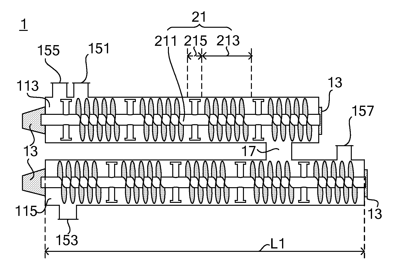
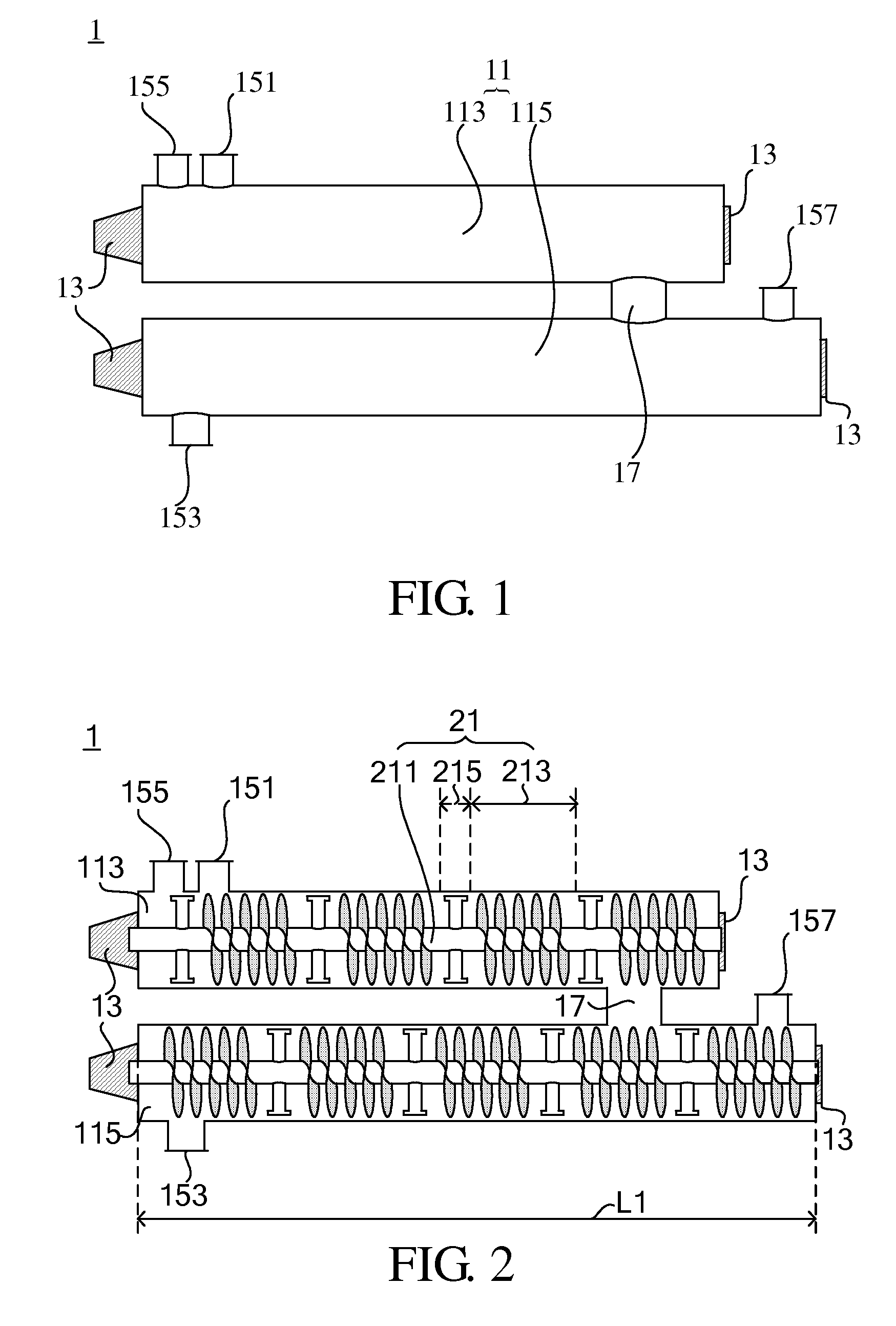
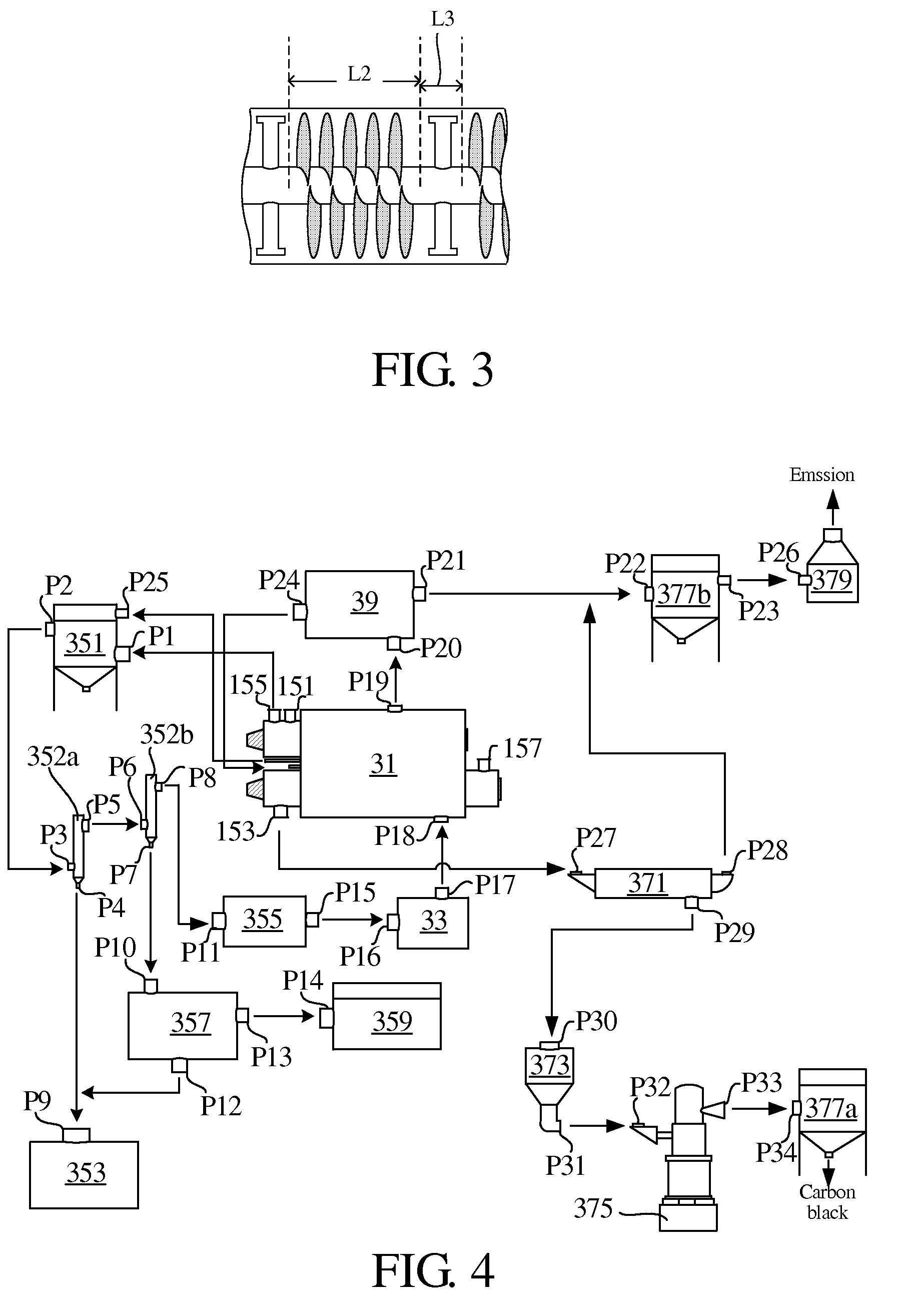
[0019]The pyrolysis furnace of the present invention comprises a reaction chamber with a charge opening and a discharge opening, and one or more axial transporting structures installed in the reaction chamber. Each of the transporting structures has a central axis, and comprises a plurality of spiral structures and a plurality of paddle structure disposed along the central axis direction. Accordingly, one or more spiral segments consisting of the screw structures and one or more paddle segments consisting of the paddle structures are formed. Each of the spiral / paddle structures has the same or different spacing from neighboring spiral / paddle structures. Preferably, each of the paddle segments is substantially identical in length, and each of the spiral segments is substantially identical in length. In an embodiment, each of the transporting structures comprises a plurality of spiral segments and a plurality of paddle segments that are alternately arranged with each other.

[0020]The r...


PUM


Abstract

A continuous steam pyrolysis device and a pyrolysis furnace therefor are provided. The device comprises a heat generator, a combustion chamber and a superheated steam generator. The combustion chamber comprises a reaction chamber with a charge opening and a discharge opening, and one or more axial transporting structures installed in the reaction chamber, wherein each transporting structure has a central axis and comprises one or more proceeding zones and one or more blending zones. The total length of the blending zones along the central axis direction ranges from about 5% to about 35% of the length of the transporting structure.

Description

CROSS-REFERENCE TO RELATED APPLICATIONS [0001]This application claims priority to Taiwan Patent Application No. 097112500 filed on 7 Apr. 2008, the contents of which are incorporated herein by reference in its entirety.BACKGROUND OF THE INVENTION [0002]1. Field of the Invention[0003]The present invention relates to a continuous steam pyrolysis apparatus, and more particularly, relates to a continuous steam pyrolysis apparatus having a unique transporting structure, which is especially used for the treatment of waste tires.[0004]2. Descriptions of the Related Art[0005]Waste tires are generally recycled in two methods. The first method is the physical processing method, in which the waste tires are broken up, then the steel wires, nylon and rubber are separated, and finally the rubber is recycled in a form of raw rubber. However, as a recycled material, the recycled rubber has poor quality and is inappropriate for use as a raw material to produce tires. The recycled rubber thus obtain...

Claims


Application Information

Patent Timeline
IPC IPC(8): C10B35/00C10B9/00
CPCC10B47/44C10G1/10C10B53/07C10B51/00Y02P20/143
Inventor WU, CHUN-YAOULADZIMIR, KALITKO
Owner ENRESTEC
Learn More