LED package and light source device using same

a technology of led packages and light source devices, applied in the direction of basic electric elements, electrical equipment, semiconductor devices, etc., can solve the problems of shortening the life of the led, weakening the current at given voltage, and deteriorating the internal quantum efficiency of the led

Active Publication Date: 2009-10-08
ADVANCED OPTOELECTRONICS TECH
View PDF2 Cites 48 Cited by
  • Summary
  • Abstract
  • Description
  • Claims
  • Application Information

AI Technical Summary

Problems solved by technology

High working temperatures can deteriorate internal quantum efficiency of the LED and shorten the lifespan thereof.
Such reduced resistance correspondingly results in stronger current at given voltages as well as the generation of excessive heat.
If the excessive heat is not effectively dissipated, heat accumulation can lead to deterioration of the LED.
While excessive heat from lighting elements 123 is dissipated through the encapsulant 124 and the printed circuit board 121, thermal conductivity thereof is less than optimal, such that the excessive heat is not effectively dissipated.

Method used


Image

  • LED package and light source device using same
  • LED package and light source device using same
  • LED package and light source device using same

Examples


Embodiment Construction

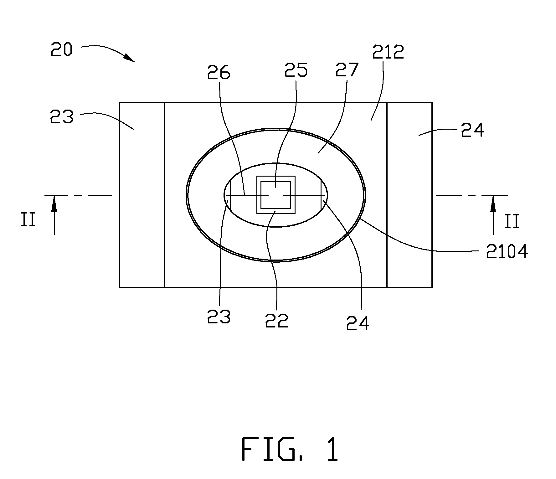
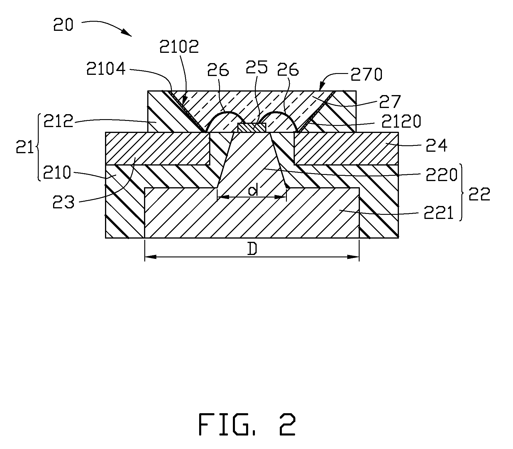
[0022]Referring to FIGS. 1 and 2, a first exemplary embodiment of an LED package 20 is provided. The LED package 20 includes a dielectric plate 21, a heat conductor 22, a first electrode 23, a second electrode 24, a LED chip 25, and a number of metal wires 26.

[0023]The dielectric plate 21 includes a holding portion 210 and a light-reflecting portion 212 located thereon. The holding portion 210 and the light-reflecting portion 212 are integrally formed. The light-reflecting portion 212 defines a receiving groove 2120 extending to the holding portion 210, such that the holding portion210 is exposed at the bottom of the receiving groove 2120. The light-reflecting portion 212 includes a reflective layer 2104 positioned in the receiving groove 2120 and located on a conical inner sidewall 2102 thereof. The dielectric plate 21 is electrically insulating, such as polyphthalamide (PPA), liquid crystal polymer (LCP) or others. Here, the dielectric plate 21 is an insulated substrate of polypht...


PUM


Abstract

An exemplary LED package includes a dielectric plate, a heat conductor, a first planar electrode and a second planar electrode, a LED chip, and metal wires. The dielectric plate comprises a receiving groove defined therein. The heat conductor is positioned in the dielectric plate opposite to the receiving groove, and the heat conductor comprises a holding portion exposed on bottom of the receiving groove. The first and second planar electrodes are respectively received in the dielectric plate extending to the receiving groove and are spaced from the heat conductor. The first and second electrodes are respectively electrically connected to the LED chip by the metal wires. The LED chip is mounted on the holding portion of the heat conductor.

Description

BACKGROUND[0001]1. Technical Field[0002]The disclosure relates to light emitting diode (LED) packages with high heat-dissipation efficiency.[0003]2. Description of Related Art[0004]Light emitting diodes, and specifically the electrical and optical characteristics and lifespan thereof, are easily influenced by temperature. High working temperatures can deteriorate internal quantum efficiency of the LED and shorten the lifespan thereof. Furthermore, resistance of the semiconductor generates a negative temperature coefficient and tends to be reduced with an increase in the working temperature. Such reduced resistance correspondingly results in stronger current at given voltages as well as the generation of excessive heat. If the excessive heat is not effectively dissipated, heat accumulation can lead to deterioration of the LED.[0005]Referring to FIG. 14, a typical light source device 10 includes a shell 11, a light source module 12, and a cover 13. The light source module 12 is receiv...

Claims


Application Information

Patent Timeline
Patent Type & Authority Applications(United States)
IPC IPC(8): H01L33/00H01L33/48H01L33/64
CPCH01L25/0753H01L33/483H01L33/642H01L2224/48091H01L2924/01322H01L2924/00014H01L2924/00
Inventor CHANG, CHUNG-MINHSU, CHIH-PENGWANG, CHUN-WEI
Owner ADVANCED OPTOELECTRONICS TECH
Why Eureka
Try Eureka