
Solid State Lighting Circuit and Controls

Active Publication Date: 2009-10-08
METROSPEC TECH
View PDF99 Cites 47 Cited by
  • Summary
  • Abstract
  • Description
  • Claims
  • Application Information

AI Technical Summary

Benefits of technology

[0021]In some embodiments, a solid state lighting circuit may include one or more of the following features: (a) a plurality of emitters operably connected to a power supply, and (b) the power supply operably coupled in series with a current limiting device, where one or more of the emitters is bypassed with a switched circuit, and (c) at least one MOSFET switch oper

Problems solved by technology

The adoption of high power solid state lighting (SSL) or high power LED lighting to global applications, including indoor and outdoor tasks and area lighting, is limited by high system costs relative to the lower costs of less efficient, traditional lighting sources.
While LED efficiency is nearing of fluorescent sources on the order of 60-100 lm / W, LED component costs are relatively high.
Further, because LEDs are highly non-linear devices in their light intensity response to increased and decreased voltage, complex and potentially energy wasteful circuits are often used to “dim” and control light output of SSL fixtures.
These systems are often associated with varying degrees of flicker or variation of light color.
Further, PWM usually requires a separate timing control adding complexity, increasing size, reducing reliability, and consuming extra energy.
PWM systems also (because of the switching of currents) create electromagnetic radiation possibly interfering with radio and other electronic devices.
However, these systems are generally complex, are costly to manufacture, have a number of points of failure and do not integrate well into existing wiring and dimming control systems used for other types of lighting.
However, to achieve current control, resistors consume energy and in most implementations severely affect the energy efficiency of the circuit.
Also, resistors do not fully control current variance as a function of voltage variance; they simply reduce the variance to a more linear result.
Linear regulators are more expensive and may require more components than using simple resistors to control current.
And, because linear regulators behave mainly as variable resistors, they can be just as costly in their consumption of energy, particularly if the stacked Vf of the emitters is substantially lower than the voltage applied at the input of the regulator.
However, switching regulators suffer five significant drawbacks.
Switching regulators generally involve more components and are almost always more expensive than linear regulators.
Switching regulators are not more efficient than linear regulators when small voltage drops are involved.
Switching regulators generally produce electromagnetic interference (EMI) and in some cases audible noise as the result of their switching frequency and components.
And, switching regulators are less reliable than other choices because of additional complexity and aging effects and environmental sensitivity of inductive and capacitive storage devices.

Method used


Image

  • Solid State Lighting Circuit and Controls
  • Solid State Lighting Circuit and Controls
  • Solid State Lighting Circuit and Controls

Examples


Embodiment Construction

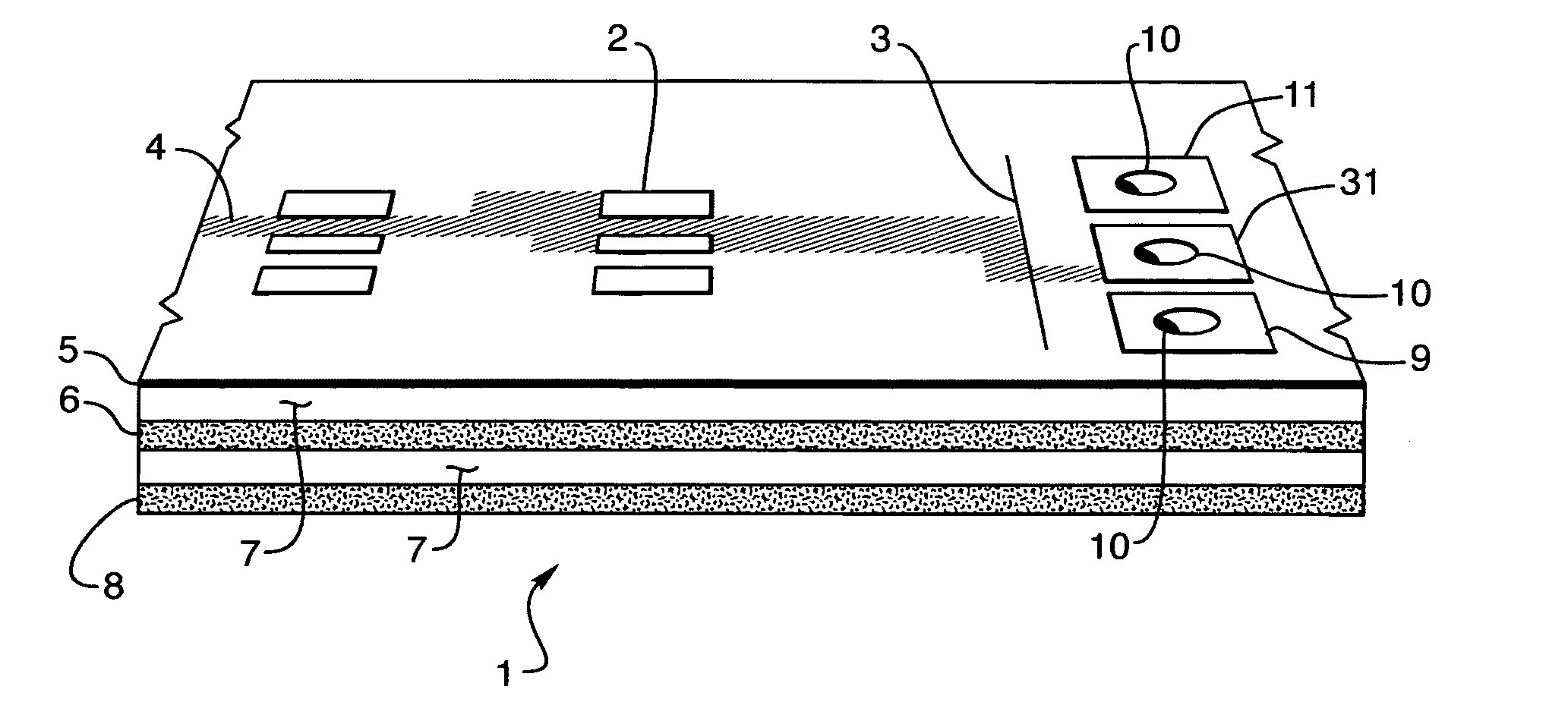
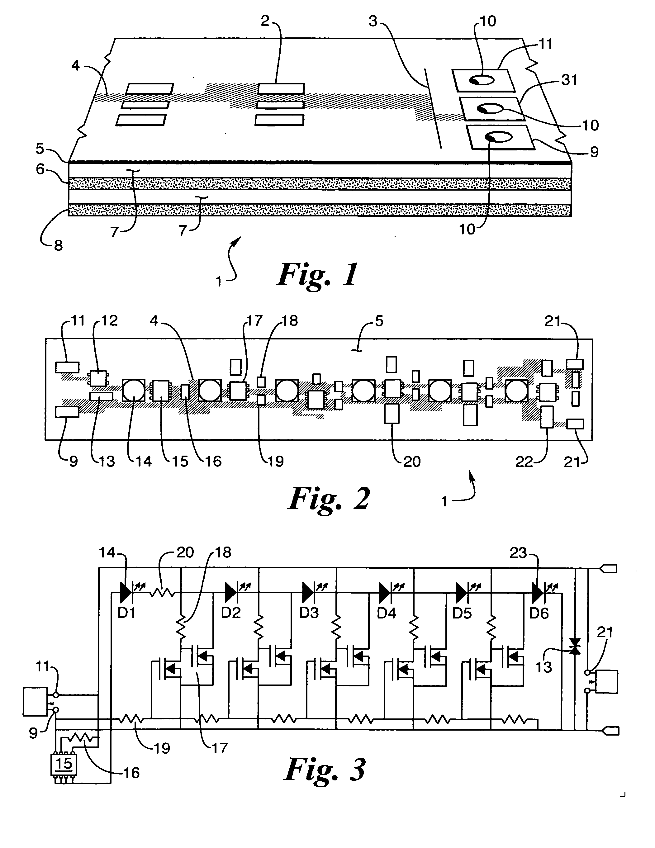
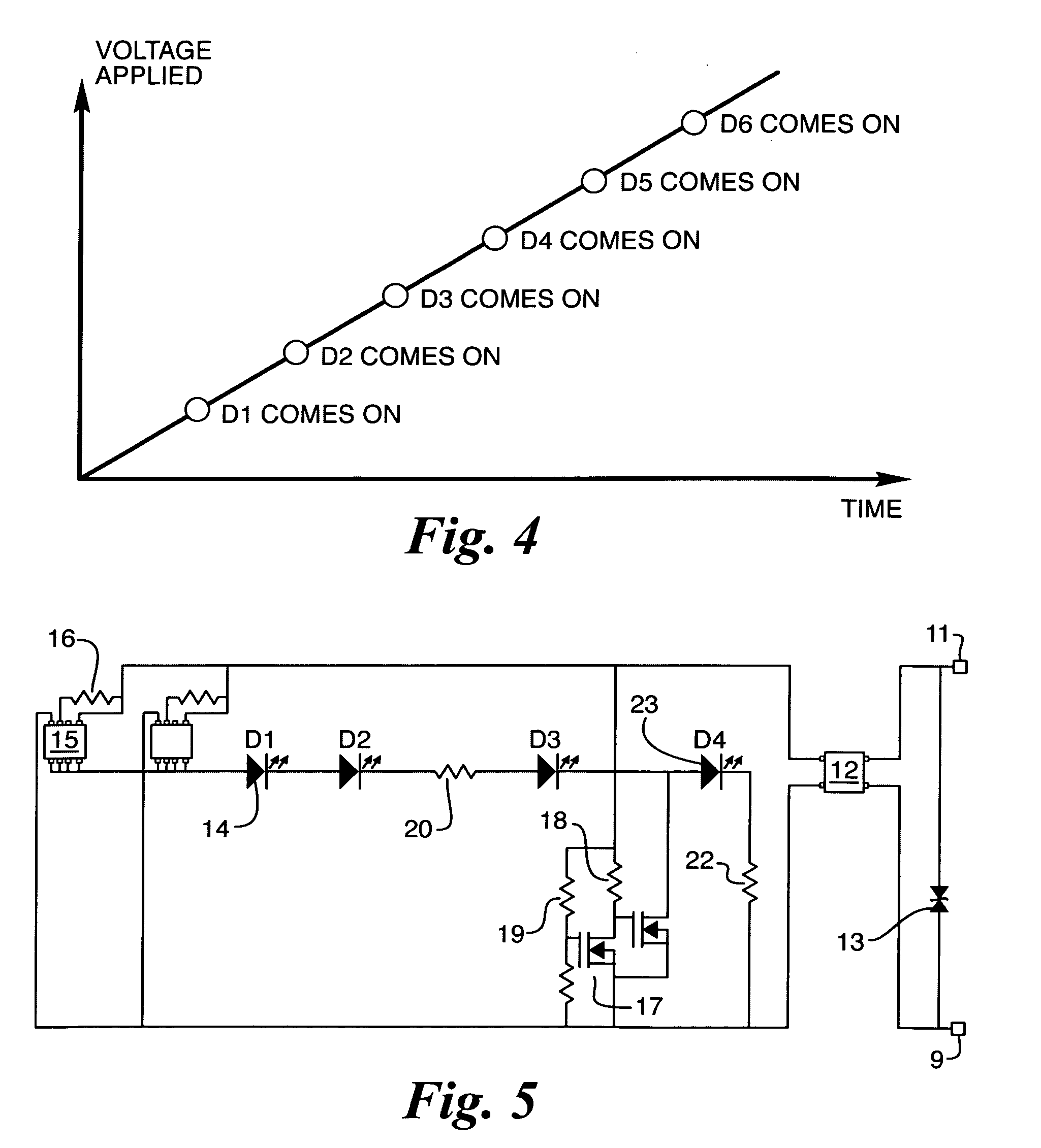
[0037]The following discussion is presented to enable a person skilled in the art to make and use the present teachings. Various modifications to the illustrated embodiments will be readily apparent to those skilled in the art, and the generic principles herein may be applied to other embodiments and applications without departing from the present teachings. Thus, the present teachings are not intended to be limited to embodiments shown, but are to be accorded the widest scope consistent with the principles and features disclosed herein. The following detailed description is to be read with reference to the figures, in which like elements in different figures have like reference numerals. The figures, which are not necessarily to scale, depict selected embodiments and are not intended to limit the scope of the present teachings. Skilled artisans will recognize the examples provided herein have many useful alternatives and fall within the scope of the present teachings.

[0038]Embodime...


PUM


Abstract

In some embodiments, a solid state lighting circuit may include one or more of the following features: (a) a plurality of emitters operably connected to a power supply (b) the power supply operably coupled in series with a current limiting device, where one or more of the emitters is bypassed with a switched circuit, and (c) at least one MOSFET switch operably coupled to the voltage divider circuit.

Description

CROSS-REFERENCE TO RELATED APPLICATIONS[0001]The present application claims priority to U.S. Patent Application Ser. No. 61 / 043,006, filed on Apr. 7, 2008, titled Configurations and Controls for High Power LED Systems, listing Henry V. Holec and Wm. Todd Crandell as co-inventors, herein incorporated by reference in its entirety. The present application is related to co-pending U.S. patent application Ser. No. 12 / 372,499, filed on Feb. 17, 2009, titled Printed Circuit Board Flexible Interconnect Design, listing Henry V. Holec and Wm. Todd Crandell as co-inventors, and to co-pending U.S. patent application Ser. No. 12 / 406,761, filed on Mar. 18, 2009, titled Printed Circuit Board Interconnect Construction, listing Henry V. Holec and Wm. Todd Crandell as co-inventors, herein incorporated by reference in their entirety.FIELD OF THE INVENTION[0002]Embodiments of the present invention relate to designs and methods of efficiently powering and controlling light output for use with light emit...

Claims


Application Information

Patent Timeline
IPC IPC(8): H05B37/02H05B44/00
CPCF21K9/30F21V23/005F21Y2101/02F21Y2111/005H05B33/0803H05B33/083H05B33/0896H05K1/0263H05K2201/09309H05K2201/10106H05K2201/10166H05B33/0815H05B37/02F21K9/20F21Y2115/10F21Y2107/30H05B45/48H05B45/395Y02B20/30H05B45/60
Inventor HOLEC, HENRY V.CRANDELL, WM. TODD
Owner METROSPEC TECH
Learn More