Magnetic resonance system and operating method therefor

Active Publication Date: 2009-10-08
SIEMENS HEALTHCARE GMBH
View PDF9 Cites 29 Cited by
  • Summary
  • Abstract
  • Description
  • Claims
  • Application Information

AI Technical Summary

Benefits of technology

[0038]At least one digital module is preferably installed together with at least one analog module that it controls in an external piece of equipment. This in particular applies at the transmitter side for a power amplifier that can be integrated into an apparatus together with the associated digital transmission module, and on the receiver side for a signal preamplifier (nece

Problems solved by technology

With this centrally organized control system, a future maximum expansion must already be taken into account in the design since the capacities of the central control computer are limited both spatially and with regard to power.
This maximum expansion, however, cannot be exactly planned for all system functionalities at the point in time of the design since the technical develop

Method used


Image

  • Magnetic resonance system and operating method therefor
  • Magnetic resonance system and operating method therefor
  • Magnetic resonance system and operating method therefor

Examples


Embodiment Construction

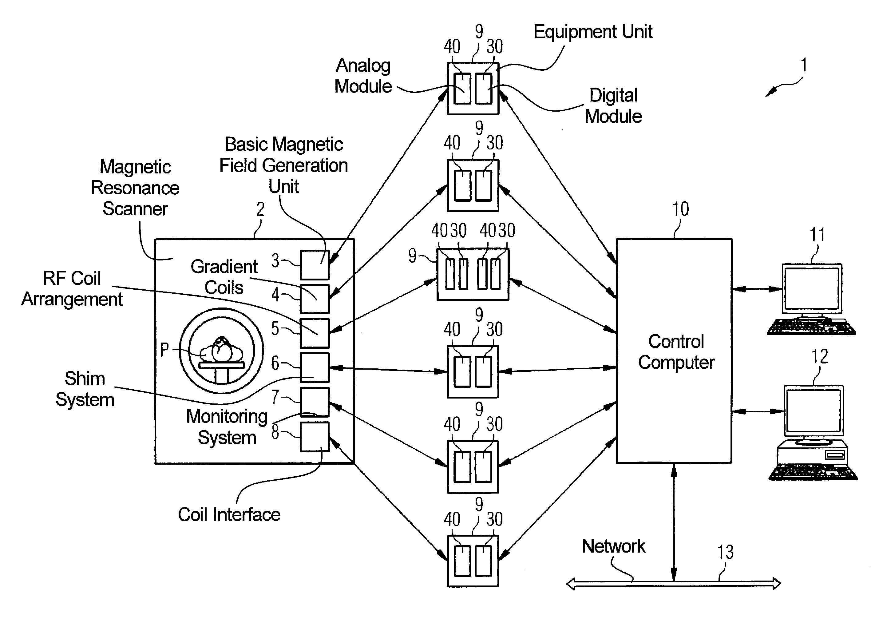
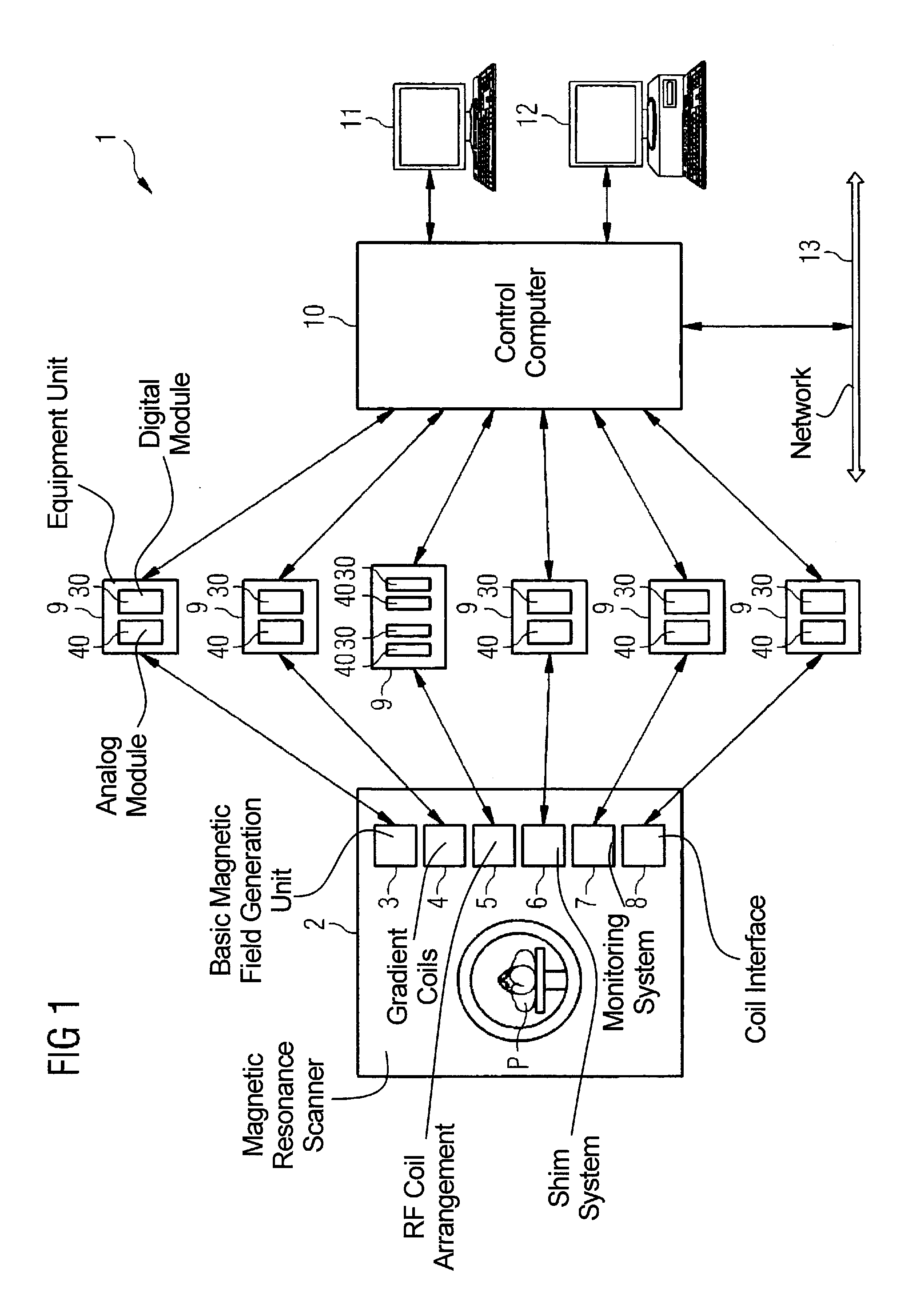
[0042]A magnetic resonance system 1 according to the invention is presented in a general schematic in FIG. 1.

[0043]The system includes the actual magnetic resonance scanner 2 in which a patient P or test subject is supported on a patient bed in an examination space or patient tunnel during an examination. In this magnetic resonance scanner 2 there are a number of components 3, 4, 5, 6, 7, 8 that are only schematically shown. These components 3, 4, 5, 6, 7, 8 include a basic magnetic field generation unit 3 which ensures that an optimally homogeneous basic magnetic field is present within the patient tunnel. Furthermore, the magnetic resonance scanner 2 contains gradient coils 4 with which a magnetic field gradient can be applied in a defined manner within the patient tunnel, as well as a radio-frequency (RF) coil arrangement 5 (for example a whole-body antenna) via which radio-frequency fields can be emitted in the patient tunnel. Also among the components are: a shim system 6 to im...


PUM


Abstract

A magnetic resonance system has a number of components including a basic magnetic field generation unit, gradient coils as well as a radio-frequency coil arrangement. The components are respectively controllable according to a control sequence via at least one digital module and at least one analog module. The analog modules are arranged external to a control computer that controls the digital modules. The digital modules are likewise arranged external to the control computer and are associated with the analog module or modules controlled via the control computer. The digital modules are networked via the following networks for communication of the digital modules among one another and/or with the control computer: a synchronous first network to synchronize the digital modules, an isochronous or semi-isochronous second network, a third network, wherein the digital modules are connected with the control computer via serial peripheral component interfaces and a signal transmission between the peripheral component interface of the respective digital module and the associated peripheral component interface of the control computer thereby occurs on optical paths.

Description

BACKGROUND OF THE INVENTION[0001]1. Field of the Invention[0002]The present invention concerns a magnetic resonance system with a number of components including a basic magnetic field generation unit, gradient coils as well as a radio-frequency coil arrangement. The components are thereby respectively controllable according to a control sequence via at least one digital module and at least one analog module, and the analog modules are arranged external to a control computer controlling the digital modules. Moreover, the invention concerns a method for the operation of such a magnetic resonance system.[0003]2. Description of the Prior Art[0004]Magnetic resonance tomography is a widespread method to acquire images of the inside of a body. In this method the body to be examined is exposed to a relatively high basic magnetic field, for example of 1.5 Tesla, or even of 3 Tesla in newer systems, known as high magnetic field systems. A radio-frequency excitation signal (known as the B1 fie...

Claims


Application Information

Patent Timeline
IPC IPC(8): G01R33/36
CPCG01R33/36
Inventor BAUMGARTL, RUDIDEMHARTER, NIKOLAUSPIRKL, GEORGWERNER, ROLAND
Owner SIEMENS HEALTHCARE GMBH
Why Eureka
Try Eureka