Constant gm oscillator

a constant gm oscillator and oscillator technology, applied in the field of oscillators, can solve the problem that the architecture is subject to frequency changes, and achieve the effect of reducing the pvt effect of the source coupled oscillator

Inactive Publication Date: 2009-10-08
SEMICON COMPONENTS IND LLC
View PDF14 Cites 10 Cited by
  • Summary
  • Abstract
  • Description
  • Claims
  • Application Information

AI Technical Summary

Benefits of technology

[0014]The PVT effects on source coupled oscillators may be reduced by controlling the above four major parameters. The present invention provides for replacing the drain resistors of FIG. 1 with active components

Problems solved by technology

This architecture, however, is subject to frequency cha

Method used


Image

  • Constant gm oscillator
  • Constant gm oscillator
  • Constant gm oscillator

Examples


Embodiment Construction

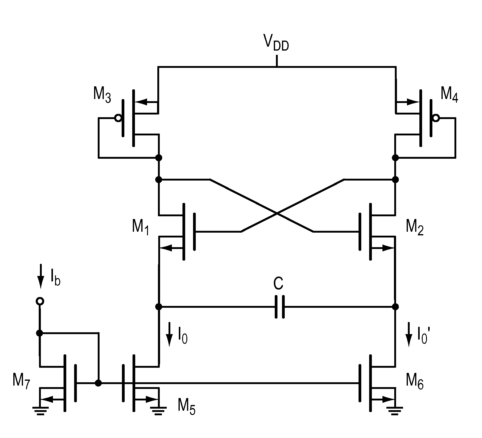
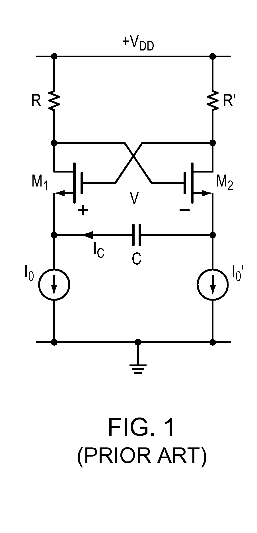
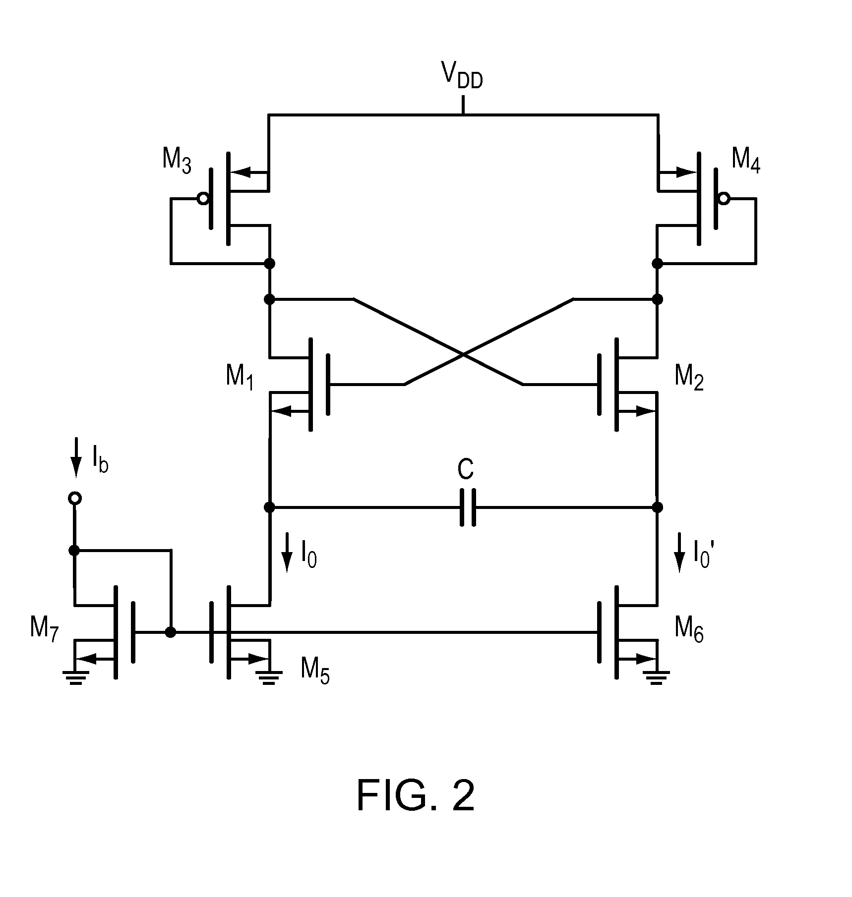
[0026]FIG. 2 is a schematic of a source coupled oscillator core. It is an adaptation of FIG. 1 where the drain resistors, R, and R′, are replaced by diode connected FETs, M3 and M4, respectively. The effective resistance of the diode connected M3 and M4 are related to 1 / gm. And the current sources, Io and Io′ are replaced by current mirrors M5 and M6, where the drain currents Io and Io′ are mirrors of Ib sourced from a constant gm circuit and is designed to be independent of Vdd. With these changes, the PVT effects of the resistors and the current sources are lumped with the PVT effects of the gm. In such an instance, the gm is made constant reducing the PVT effects on the oscillator frequency.

[0027]Although FIGS. 1 and 2 use MOSFETs, these circuit may be constructed with bipolar or hybrid transistors.

[0028]In FIG. 2 the currents Io and Io′ are set by current Ib injected into the cell via M7. Cross coupled pair M1 and M2 are isolated well transistors that eliminates the back gate bi...


PUM


Abstract

The present invention provides a constant gm circuit that generates a bias current for a emitter/source-coupled multivibrator oscillator. The stable gm bias limits the temperature dependence of the oscillator. Trimming a resistor in the constant gm circuit compensates for process variations, and current sources may be provided that are mirrors of the bias current that are also substantially independent of the supply voltage. The present invention provides an oscillator with less that 1% frequency changes due to PVT variations.

Description

RELATED APPLICATIONS[0001]This application is related to and claims the benefit of the filing of Provisional Application Ser. No. 61 / 042,050, filed Apr. 3, 2008; this provisional application is of common title, ownership and inventorship. The provisional application is incorporated herein by reference.BACKGROUND OF THE INVENTION[0002]1. Field of the Invention[0003]The present invention is related to oscillators and more particularly source-coupled oscillators that are relatively immune to manufacturing process (process), voltage (the circuit power source) and temperature, or PVT, variations.[0004]2. Background Information[0005]FIG. 1 illustrates a known source coupled astable multi-vibrator or oscillator. This architecture, however, is subject to frequency changes due to temperature, voltage and process variations.[0006]FIG. 1 has two equal load resistors, R and R′, and the FET's, M1 and M2, are source coupled through a floating capacitor C. The circuit includes two independent curr...

Claims


Application Information

Patent Timeline
IPC IPC(8): H03B5/04
CPCH03K3/2821H03B5/24
Inventor JASA HRVOJE (HERY)
Owner SEMICON COMPONENTS IND LLC
Why Eureka
Try Eureka