Hand-held power tool

Inactive Publication Date: 2009-10-08
HILTI AG
View PDF15 Cites 132 Cited by
  • Summary
  • Abstract
  • Description
  • Claims
  • Application Information

AI Technical Summary

Benefits of technology

[0008]It is the object of the present invention to provide a hand-held power tool of the kind mentioned above which makes it possible to send operational data (information about power tool functions and operating conditions) and measurement data to an evaluation location in a simple manner.

Problems solved by technology

It is disadvantageous that the power tool must be located in the immediate vicinity of a personal computer in order to transfer data from the power tool to the personal computer.

Method used


Image

  • Hand-held power tool
  • Hand-held power tool
  • Hand-held power tool

Examples


Embodiment Construction

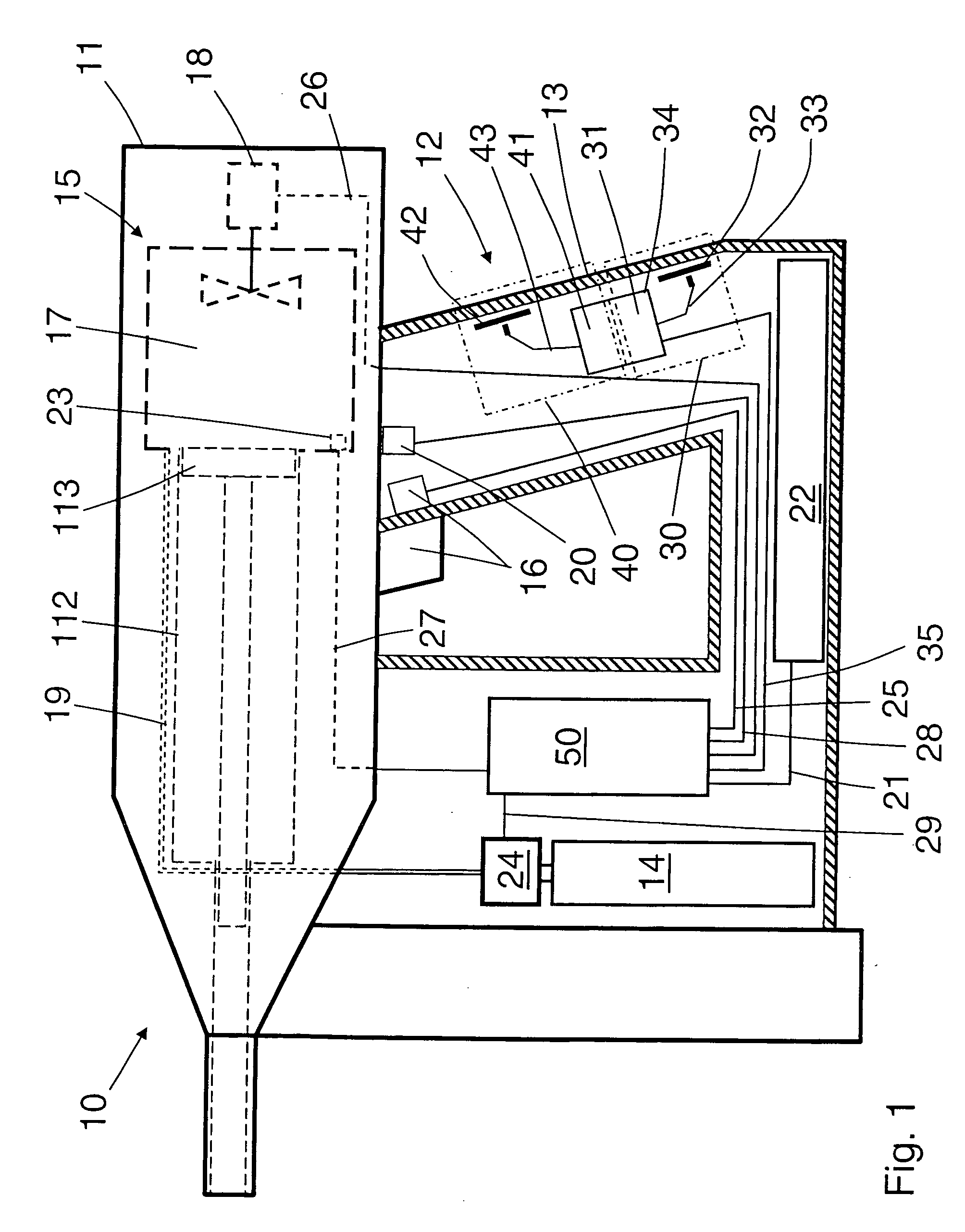
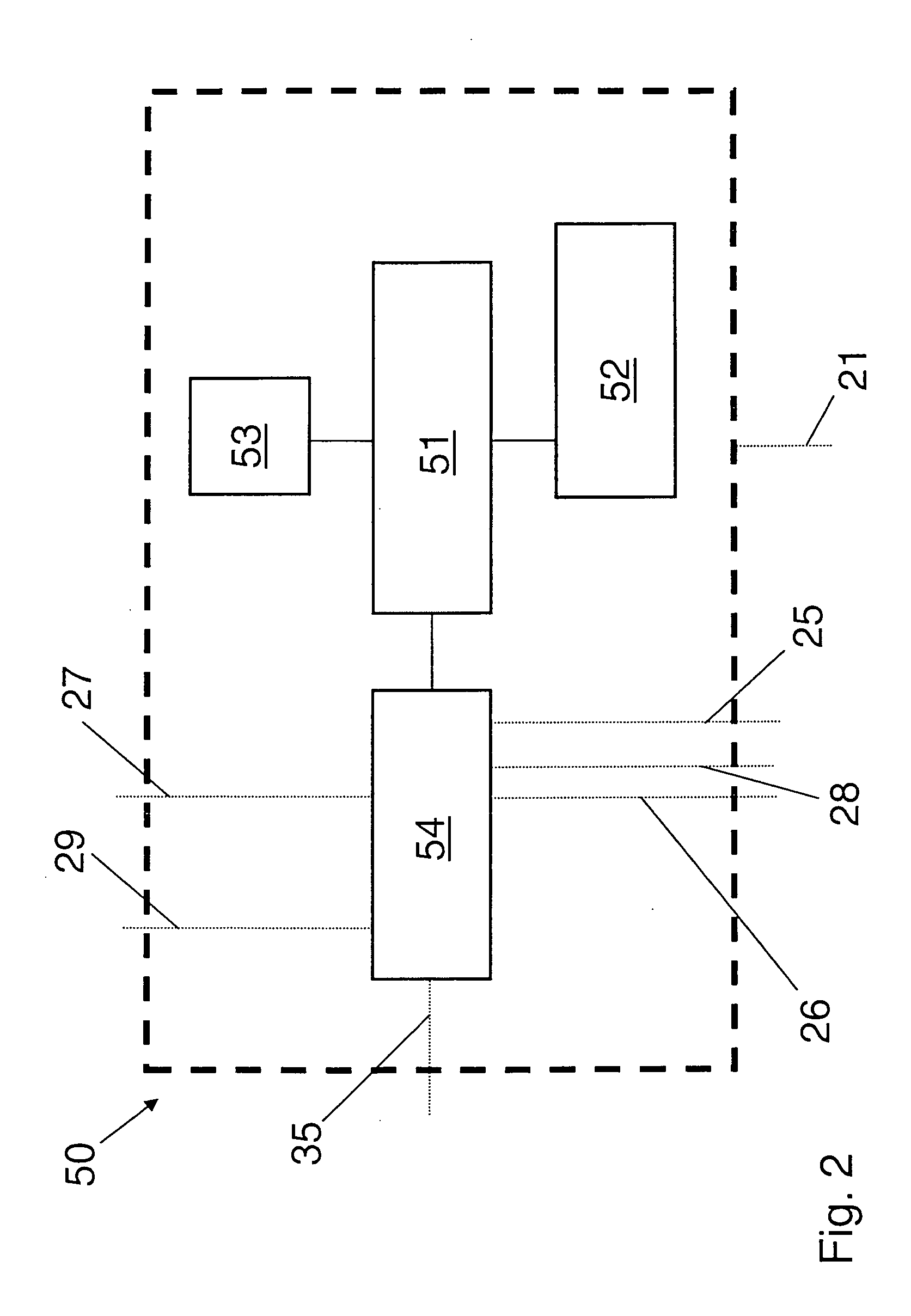
[0024]A hand-held power tool 10 according to the invention, which is shown in FIGS. 1-2, is formed as a combustion-powered setting device. The power tool 10 has a housing, designated generally by 11, which is formed of one or more parts and in which a drive 15 is arranged. A fastening element such as a nail, bolt, etc. can be driven into a workpiece by the drive 15. The fastening elements can be stored, for example, in a magazine provided at the power tool 10.

[0025]The drive includes a combustion chamber 17 and a guide cylinder 112 in which a setting piston 113 is arranged so as to be axially displaceable. As can further be seen in FIG. 1, a trigger switch 16 is arranged in a handle area 12 of the power tool 10 with which an ignition device 23, e.g., a spark plug, in the combustion chamber 17 can be triggered when the power tool 10 has been pressed against a workpiece. In addition to the trigger switch 16 mentioned above, additional switches such as, e.g., contact pressure switches,...


PUM


Abstract

A hand-held power tool (10) includes a housing (11), and a drive (15) arranged in the housing (10), sensors (20) for acquiring measurement data, a control unit (50) for processing measurement data and for controlling power tool functions, and a remote data transmission device (30) for wireless, network-supported digital remote data transmission and having a wireless transmitting and receiving unit and a radio antenna (32) communicating with the control unit (50).

Description

BACKGROUND OF THE INVENTION[0001]1. Field of the Invention[0002]The present invention is directed to a hand-held power tool including a housing, a drive located in the housing, sensor means for sensing operational conditions of the power tool, and a control unit for processing measurement data communicated by the sensor means and for controlling the power tool functions.[0003]2. Description of the Prior Art[0004]Hand-held power tools of the type mentioned above can be formed, e.g., as drive-in tools which are operated electrically or with solid, gaseous, or liquid fuels, or also with compressed air. Hand-held power tools of this kind can also be formed as rotary or at least partially percussive hand-held power tools such as, e.g., hammer drills or chisel hammers. Other examples of such power tools include drilling machines, drilling tools, demolition hammers, screw driving tools, grinding saws, circular saws, chain saws, and saber saws.[0005]In modern hand-held power tools, it is de...

Claims


Application Information

Patent Timeline
Patent Type & Authority Applications(United States)
IPC IPC(8): G08C19/00
CPCB25F5/00B25C1/08H04W4/02
Inventor GEROLD, UWEKECK, JOACHIMWELTE, NORBERT
Owner HILTI AG
Why Eureka
Try Eureka