
Digital camera with integrated accelerometers

a digital camera and accelerometer technology, applied in the field of digital camera systems with integrated accelerometers, can solve the problems of difficult miniaturisation, mercury switches usually consume a lot of space, and can cause great damage, so as to reduce moiré image defects and increase sharpness.

Inactive Publication Date: 2009-10-08
PHASE ONE
View PDF29 Cites 10 Cited by
  • Summary
  • Abstract
  • Description
  • Claims
  • Application Information

AI Technical Summary

Benefits of technology

Enables accurate orientation correction, reduced blur in images, and improved image quality by providing real-time feedback on camera movements, allowing for better handling of vibrations and orientation adjustments, thus enhancing the capabilities of digital cameras in various applications.

Problems solved by technology

The use of mercury switches has some distinct disadvantages in that mercury can cause great damage when it interacts with the human body, and for that reason it is quite unpopular in many products.
Mercury switches usually consume a lot of space in comparison with monolithic IC's.
This is due to their very mechanic structure, which makes miniaturisation difficult.
In a digital camera it is crucial to minimise the size and weight, so in respect to this, the use of mercury and other primarily mechanically based switches, is not the optimum choice.
A mercury switch based solution in a digital camera is limited to detecting a few rough orientations, i.e. landscape and portrait.
The main limitation regarding micro-mechanical accelerometers fabricated in e.g. silicon is related to their ability to absorb shock without being damaged.
Taking pictures with long shutter times and maybe even a high degree of zoom makes the image capture process very sensitive to vibrations, which will result in blurred images.
Especially handheld photography easily results in blurred images when longer shutter speeds are used.
This requires a special and expensive lens.
None of the described implementations are able to determine if the camera after a short period of vibrations returns to its initial position or the position where the majority of the exposure time has been spent.
In such a case the suggested implementations would generate a “blur” alarm, even though the image could be sharp.
In most common photographic situations it is not desirable to have an automatic correction of a slight slant, as the photographer often wants full control of the image orientation.
Measuring the inclination through the use of timing marks is not useful in digital still photography.
Mercury switches or pendulums are limited to a more rough evaluation of the orientation of the camera (basically limited to two positions).
The mercury switch and pendulum switch based solutions lack the possibility to be dynamically configured to each users need, as their functionality is fixed mechanically when they leave the factory.
With a traditional film camera it is necessary to have an expensive lens which corrects the induced vibrations by changing the optical path of incident light.
In such a case the earlier implementations would generate a “blur” alarm, even though the image could be sharp.

Method used


Image

  • Digital camera with integrated accelerometers
  • Digital camera with integrated accelerometers
  • Digital camera with integrated accelerometers

Examples


Embodiment Construction

[0088]In the following description, for purposes of explanation and not limitation, specific details are set forth in order to provide a thorough understanding of the present invention. However, it will be apparent to one skilled in the art that the present invention may be practiced in other embodiments that depart from these specific details. In other instances, detailed descriptions of well-known devices and methods are omitted so as not to obscure the description of the present invention with unnecessary details.

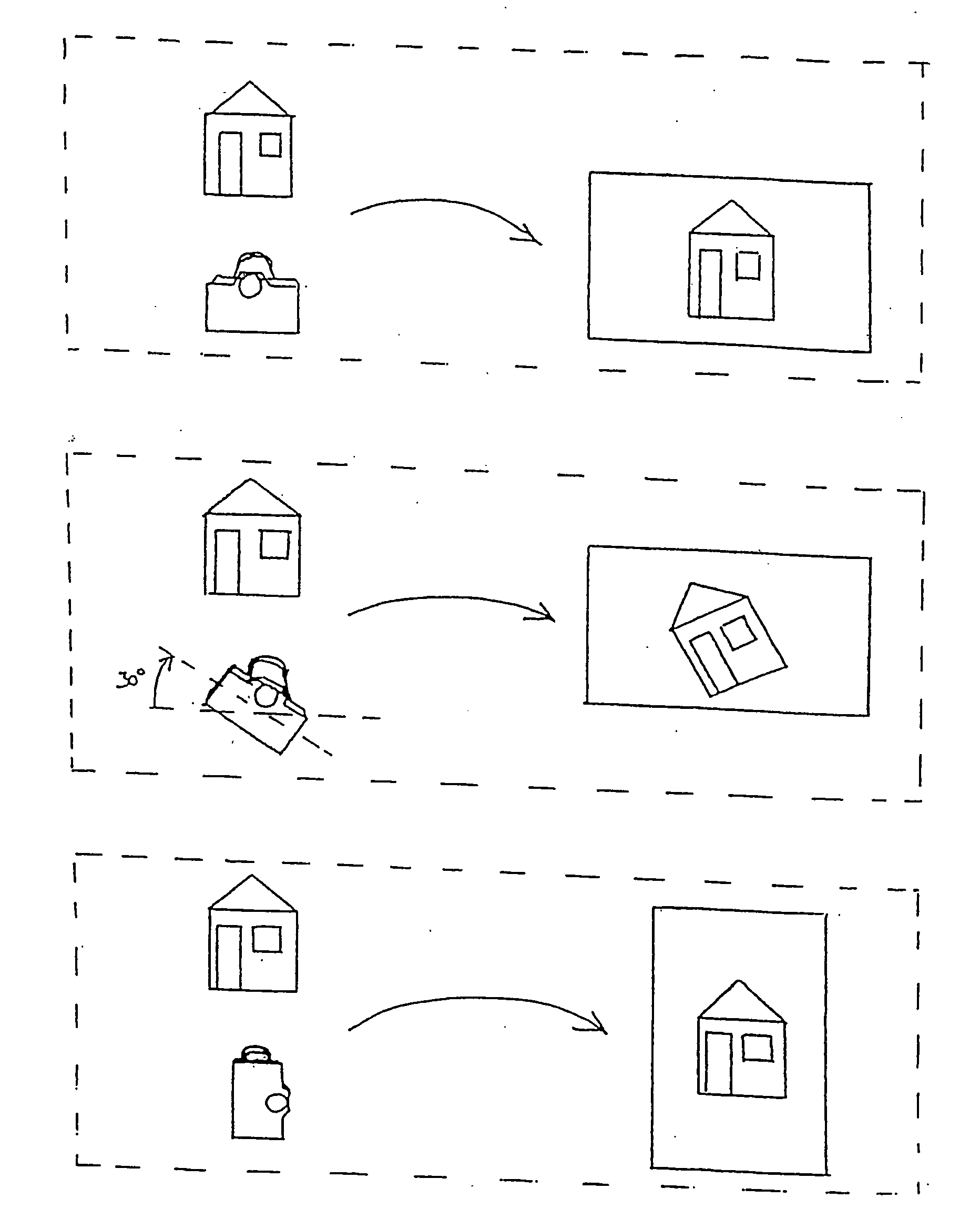
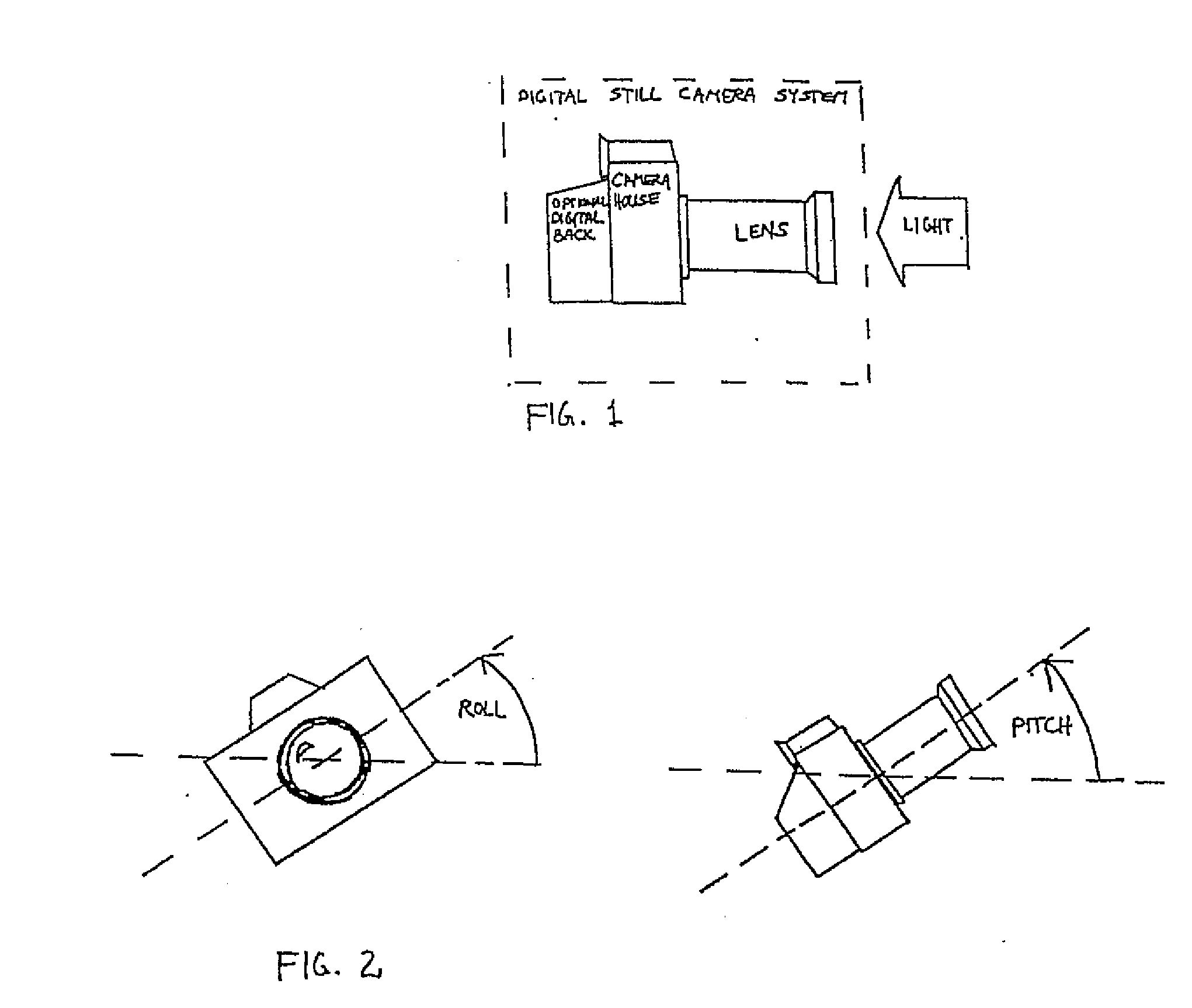
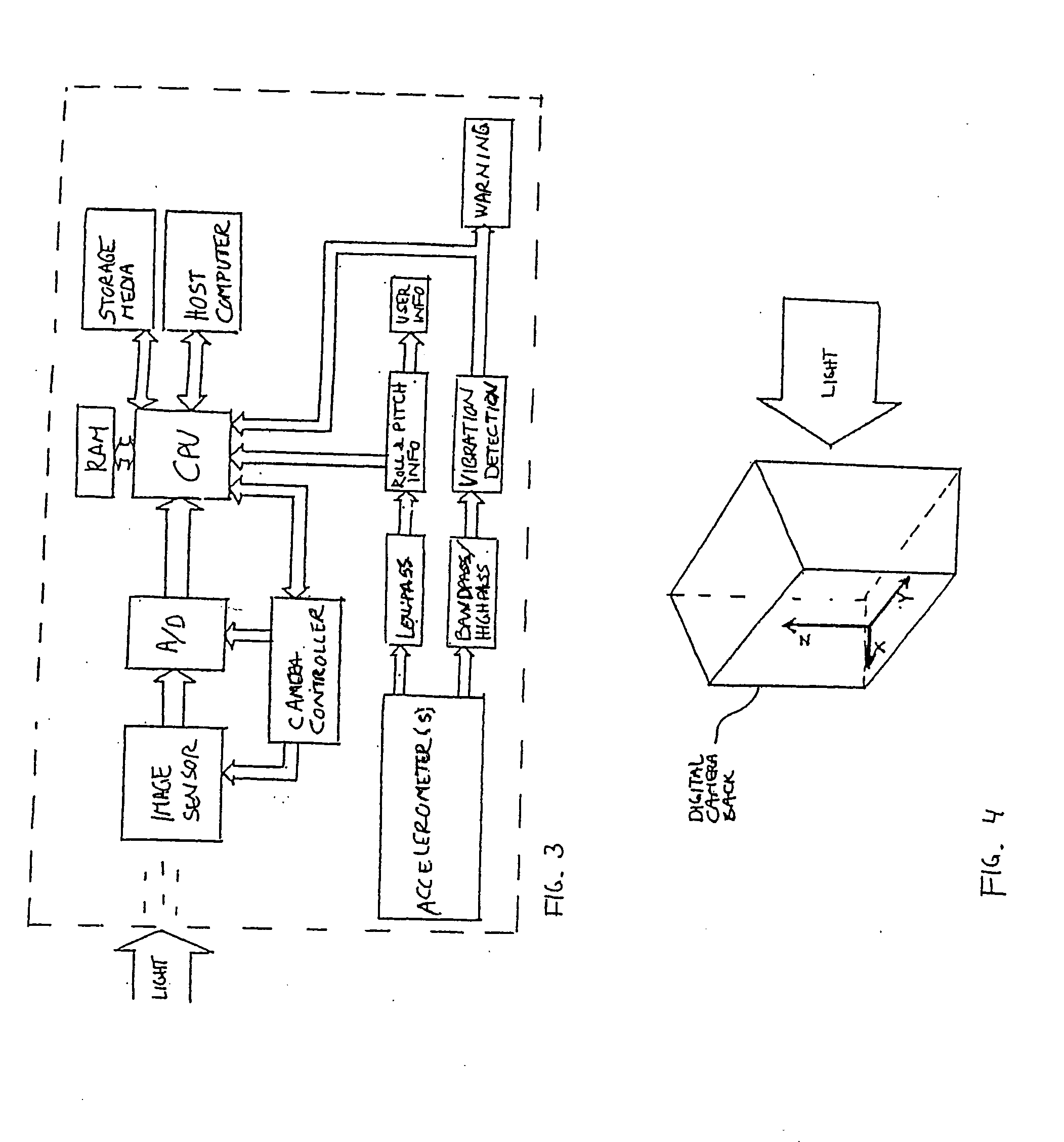
[0089]The digital still camera system as shown in FIG. 1, where the digital back is optional, incorporates a section which is able to determine the roll and pitch of the camera with respect to the field of gravity, see FIG. 2. The same section also monitors the vibrations, which occur during the time of exposure. A block diagram can be seen in FIG. 3. The sensor section is comprised of one or more accelerometers, which monitors acceleration in two or three axes placed pe...


PUM


Abstract

A digital camera system has integrated accelerometers for determining static and dynamic accelerations of the digital cameral system. Data relating to static and dynamic accelerations are stored with recorded image data for further processing, such as for correcting image data for roll, pitch and vibrations and for displaying recorded images with a predetermined orientation using information about, e.g., roll. Data may also be used on-the-fly for smear suppression caused by vibrations.

Description

CROSS-REFERENCE TO RELATED APPLICATION[0001]This is a continuation application of application Ser. No. 10 / 847,354, filed on May 18, 2004, which is a continuation-in-part application of application Ser. No. 09 / 897,435, now U.S. Pat. No. 6,747,690, filed on Jul. 3, 2001, which claims priority under 35 U.S.C. 119(e) to Provisional Application Ser. No. 60 / 217,023 filed on Jul. 11, 2000, the entire contents of which are hereby incorporated by reference in their entirety for all purposes.FIELD OF INVENTION[0002]The present invention relates to a digital camera system having integrated accelerometers for determining static and dynamic accelerations of said digital camera system. Data relating to the determined static and dynamic accelerations are stored with recorded image data for further processing, such as for correcting image data for roll, pitch and vibrations. Data may also be used on-the-fly for smear suppression caused by vibrations.BACKGROUND OF THE INVENTION[0003]When using recta...

Claims


Application Information

Patent Timeline
Patent Type & Authority Applications(United States)
IPC IPC(8): H04N5/76H04N5/228G03B17/00H04N1/387H04N1/409H04N23/40
CPCG03B17/00H04N1/3878H04N5/23293H04N5/23258H04N5/23267H04N1/4092H04N23/683H04N23/6812H04N23/633
Inventor MOLGAARD, CLAUS
Owner PHASE ONE
Learn More