Vehicle-mounted electronic apparatus and vehicle with the same mounted therein

a technology of electronic equipment and vehicle, applied in the field of electronic equipment, can solve the problems of increased time and effort, increased noise immunity, and damage to precision mechanical equipment, and achieve the effect of improving the anti-static performance of vehicle-mounted electronic equipment and preventing noise immunity performance from deteriorating

Inactive Publication Date: 2009-10-08
TOYOTA JIDOSHA KK
View PDF6 Cites 25 Cited by
  • Summary
  • Abstract
  • Description
  • Claims
  • Application Information

AI Technical Summary

Benefits of technology

[0039]According to the present invention, anti-static performance of the vehicle-mounted electr

Problems solved by technology

Note that other electronic apparatuses for a vehicle have a similar problem.
At a time when static electricity tends to build up, such as in the winter season, static electricity can be applied to a terminal of a connector grounded to the housing, resulting in a damage to the precision mechanical equipment.
When ground line 132 is connected to body earth GNDB via the housing at the control ECU 508 side and is connected to body earth

Method used


Image

  • Vehicle-mounted electronic apparatus and vehicle with the same mounted therein
  • Vehicle-mounted electronic apparatus and vehicle with the same mounted therein
  • Vehicle-mounted electronic apparatus and vehicle with the same mounted therein

Examples


embodiment 1

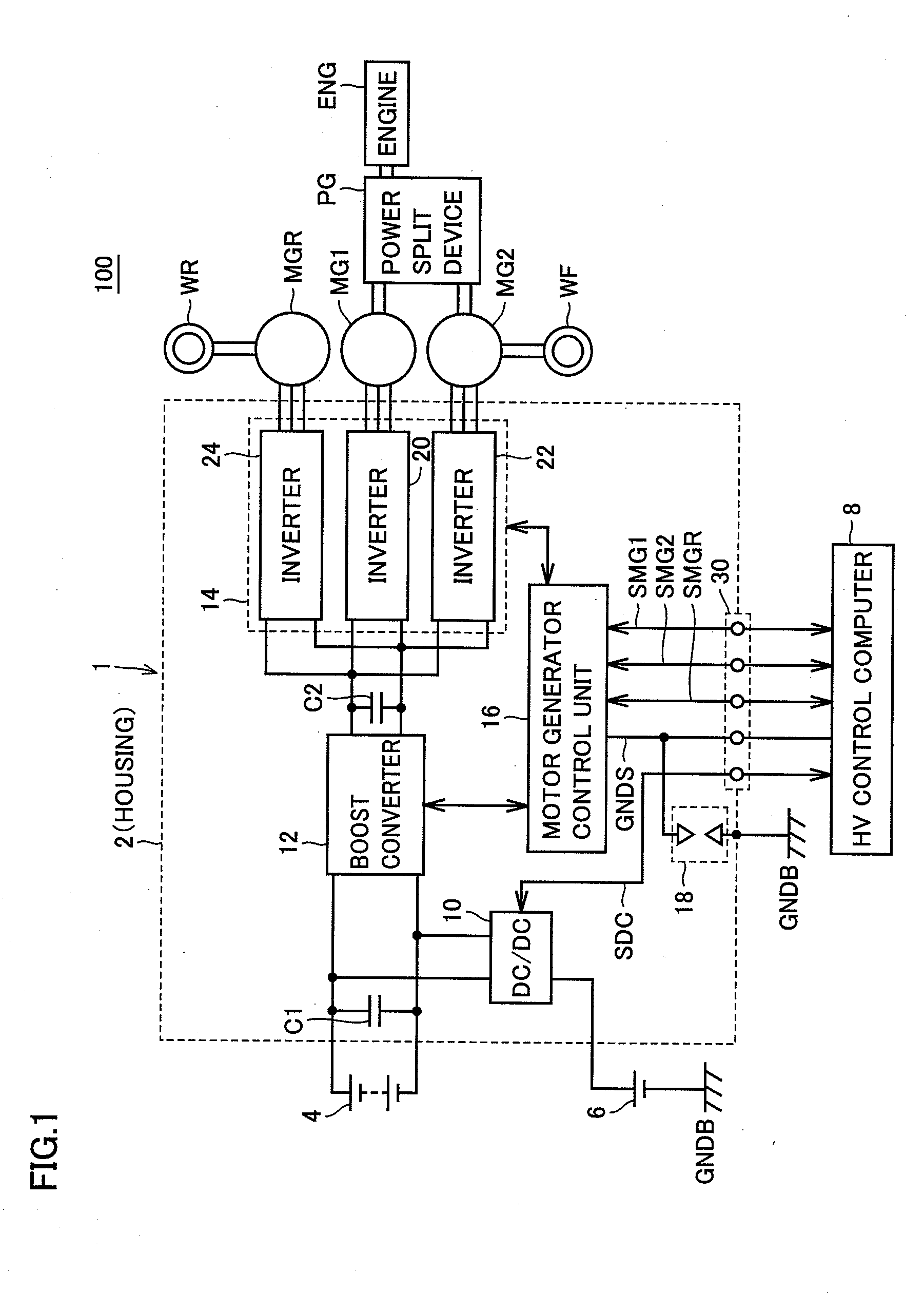
[0056]FIG. 1 is a block diagram showing a configuration of a vehicle 100 according to an embodiment of the present invention.

[0057]With reference to FIG. 1, vehicle 100 is a hybrid vehicle including a high voltage battery 4, an auxiliary battery 6, an inverter unit 1, an HV (hybrid) control computer 8, motor generators MG1, MG2 and MGR, a power split device PG, an engine ENG, a front wheel WF, and a rear wheel WR.

[0058]Power split device PG is a mechanism coupled to engine ENG and motor generators MG1 and MG2 for distributing power among these. For example, a planetary gear mechanism, which has three rotating shafts of a sun gear, a planetary carrier and a ring gear, can be used as the power split device. These three rotating shafts are connected to respective rotating shafts of engine ENG and motor generators MG1 and MG2, respectively. Note that a decelerator for the rotating shaft of motor generator MG 2 may further be incorporated inside power split device PG.

[0059]The rotating s...

embodiment 2

[0114]Although the discharge gap is formed between the conductive plate and the housing in Embodiment 1, the discharge gap can be formed in other portions.

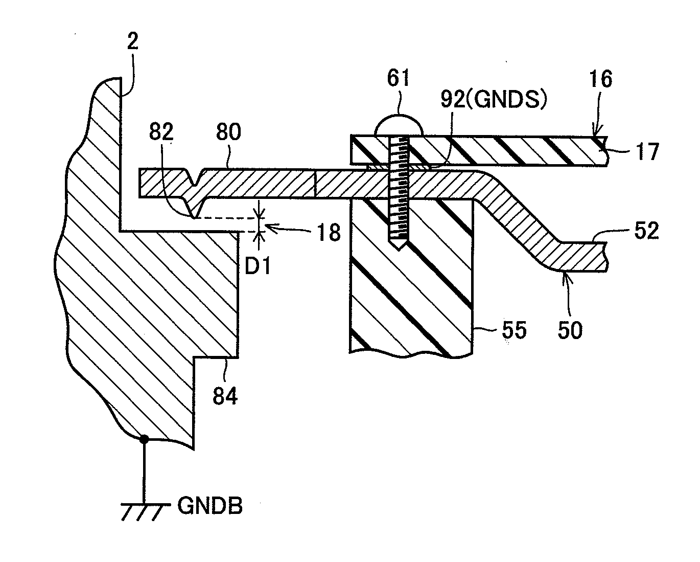
[0115]FIG. 11 is a diagram for describing the discharge gap of the inverter unit according to Embodiment 2.

[0116]FIG. 12 is a cross sectional view showing the XII-XII cross section in FIG. 11.

[0117]With reference to FIGS. 11 and 12, an inverter unit 1A further includes a conductive body earth pattern 194 forming a discharge gap 18A between the conductive body earth pattern and a conductive pattern 192 on a control circuit board 117, a spacer 155 and a screw 161 which are conductive members electrically connecting body earth pattern 194 to a housing 102. A male screw is formed in the lower part of spacer 155 and threaded into a screw hole formed in housing 102. In the upper part of spacer 155, a hole with a female screw formed on the inner wall is provided. Control circuit board 117 is clamped to spacer 155 with screw 161. As the h...


PUM


Abstract

An inverter unit includes a conductive housing (2) which is set to a ground potential, a control circuit board (17) accommodated in the housing (2), and a discharge gap (18) provided between a conductive pattern (92) formed at the control circuit board (17) and the housing (2) for discharging when a high voltage not less than a predetermined voltage is applied. Preferably, the inverter unit further includes a conductive plate (50) covering the control circuit board (17) and electrically connected with the conductive pattern (92). The discharge gap (18) is formed between the conductive plate (50) and the housing (2).

Description

TECHNICAL FIELD[0001]The present invention relates to an electronic apparatus to be mounted in a vehicle, in particular, to a configuration for protecting the vehicle-mounted electronic apparatus.BACKGROUND ART[0002]In order to provide protection against static electricity or overvoltage, a protection element for removing the overvoltage is generally provided in an electronic apparatus. An electronic control apparatus for a motor vehicle having such a protection element mounted therein is disclosed in Japanese Patent Laying-Open No. 2003-151794.[0003]This electric control apparatus is an electronic control apparatus for a motor vehicle, configured of a case ground connected to a housing, and an electronic circuit connected to the case ground. This electronic circuit has a signal line for transmitting an output signal from a sensor to an integrated circuit, a connector having a terminal of the signal line and a control ground, a capacitor aiming at EMC protection provided between the...

Claims


Application Information

Patent Timeline
IPC IPC(8): H05F3/00
CPCH05K9/0067
Inventor HIRONAKA, RYOJI
Owner TOYOTA JIDOSHA KK
Why Eureka
Try Eureka