
Wireless communication system, terminal station, and wireless communication method

a wireless communication and terminal station technology, applied in the field of wireless communication techniques, can solve problems such as prolonging training processing time, and achieve the effect of shortening the training processing processing tim

Active Publication Date: 2009-10-08
CANON KK
View PDF2 Cites 43 Cited by
  • Summary
  • Abstract
  • Description
  • Claims
  • Application Information

AI Technical Summary

Benefits of technology

[0021]According to the present invention, in a wireless communication system which includes a control station for broadcasting data and a plurality of terminal stations for receiving the data, it is possible to shorten the processing time of the training processing for determining optimum transmission / reception conditions.

Problems solved by technology

In addition, if a plurality of control stations are provided to improve the reliability of wireless communication, the training processing must be executed a number of times equal to the number of control stations, thereby prolonging the training processing time.

Method used


Image

  • Wireless communication system, terminal station, and wireless communication method
  • Wireless communication system, terminal station, and wireless communication method
  • Wireless communication system, terminal station, and wireless communication method

Examples


first embodiment

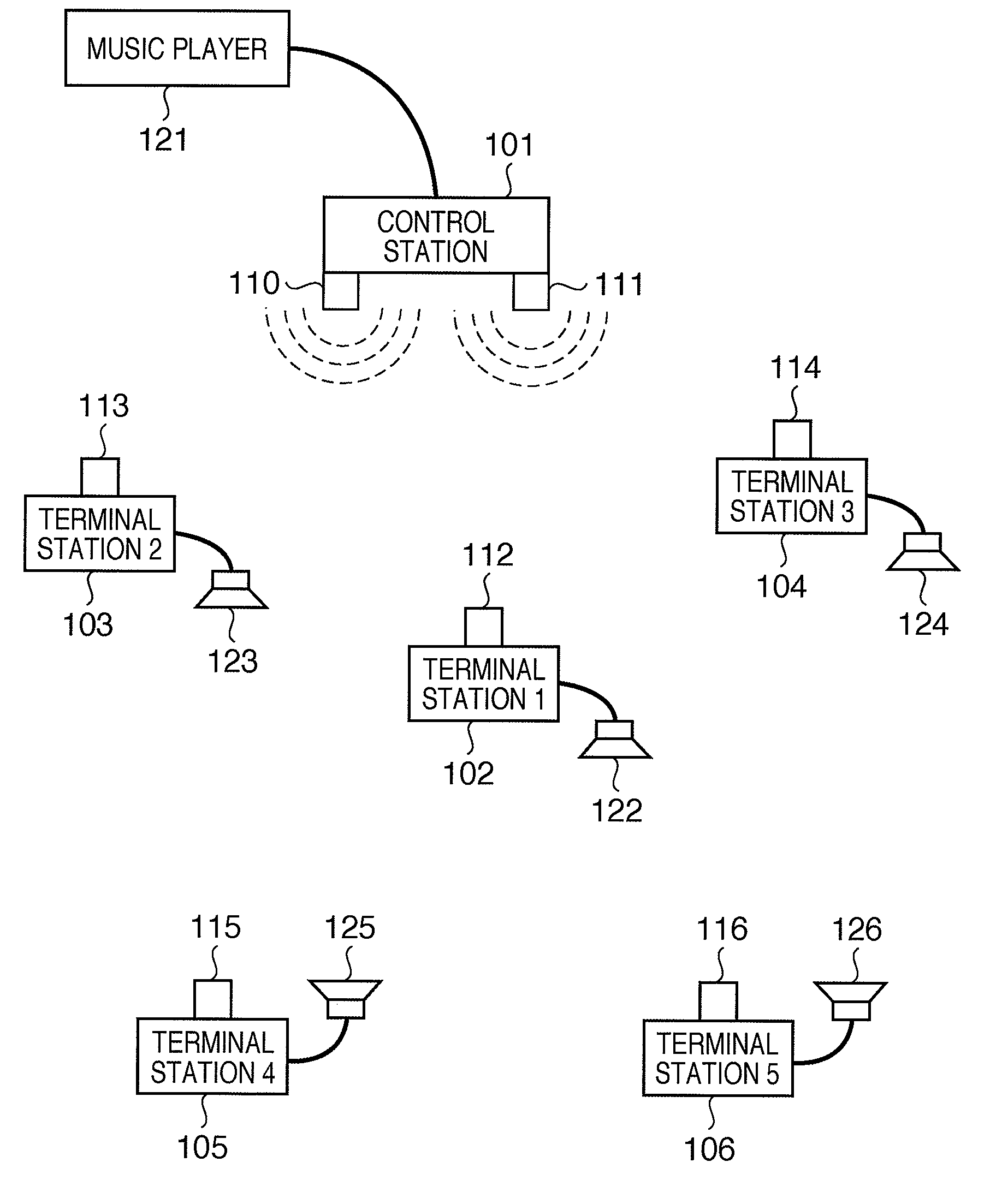
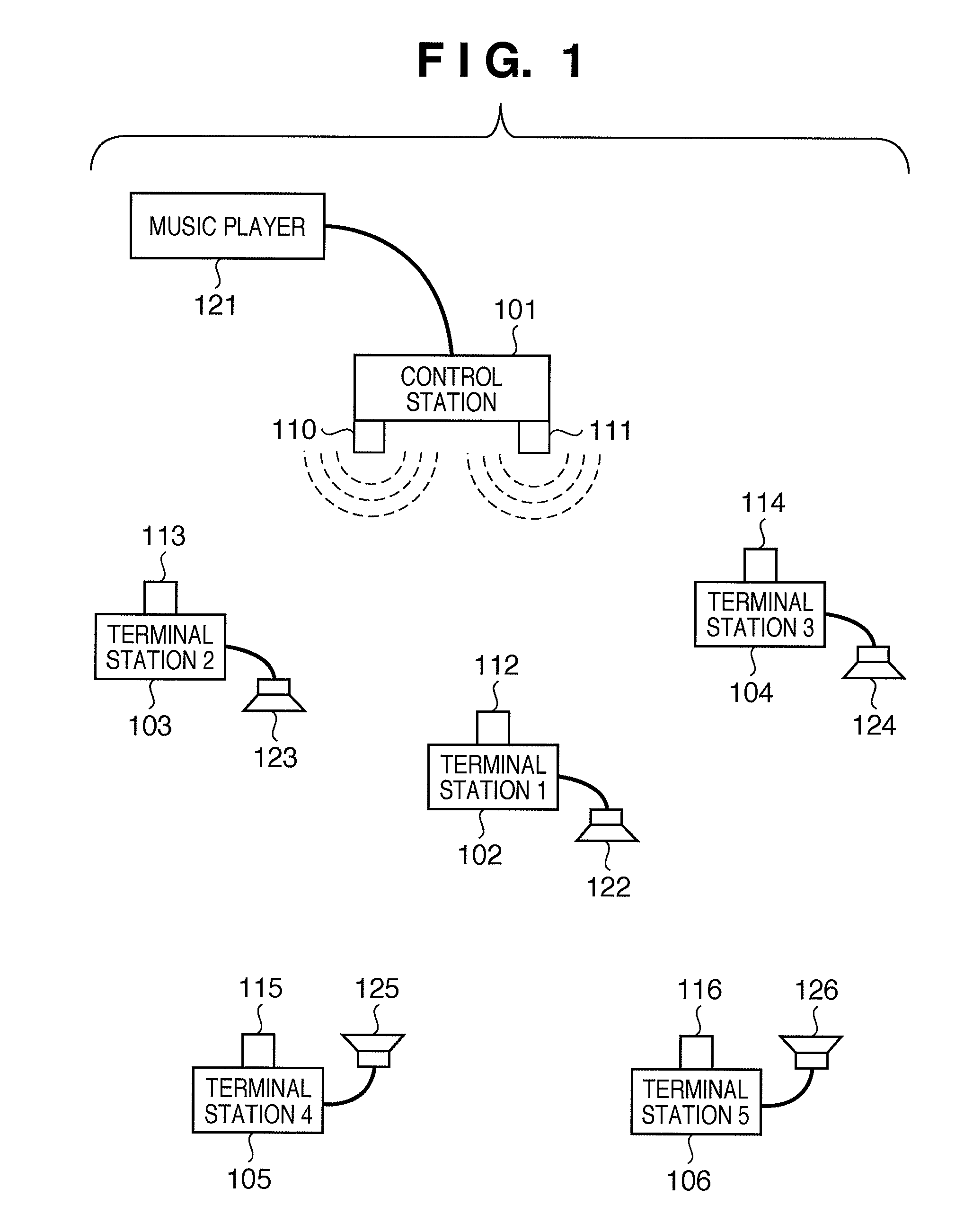
[0041]FIG. 1 shows the configuration of a wireless communication system according to the first embodiment of the present invention. Referring to FIG. 1, reference numeral 101 denotes a control station; 102 to 106, terminal stations 1 to 5, respectively; 110 and 111, a first and second antennas of the control station 101, respectively; 112 to 116, antennas of terminal stations 1 to 5 (102 to 106), respectively; 121, a music player for generating the stream data of surround music; and 122 to 126, loudspeakers.

[0042]The music player 121 is connected to the control station 101 via a cable. The stream data of surround music, which has been generated in the music player 121, is transferred to the control station 101. The control station 101 wirelessly transmits the transferred stream data to terminal stations 1 to 5 (102 to 106).

[0043]Terminal station 1 (102) is connected with the loudspeaker 122 via a cable, and acoustically reproduces the surround music at the loudspeaker 122 in accorda...

second embodiment

[0163]In the above first embodiment, a case in which wireless signals are divided based on the polarization types has been explained. The present invention, however, is not limited to this. For example, a plurality of wireless signals may be divided by a code division multiplexing scheme using spread coding, which is called CDMA. Note that CDMA is an abbreviation for Code Division Multiple Access. Details of this embodiment will be described below.

[0164]FIG. 15 shows the arrangement of a control station and FIG. 16 shows the arrangement of a terminal station, when a wireless signal multiplexing scheme using spread coding scheme is utilized.

[0165]Referring to FIG. 15, reference numeral 1501 denotes a CDMA control station; 1502, control unit 3 which controls the control station as a whole; 1503, wireless coding transmission unit 1 which performs spread coding on data by the CDMA scheme to obtain a wireless signal; and 1504, wireless coding transmission unit 2 which performs spread cod...


PUM


Abstract

The invention includes a wireless communication system including a control station which transmits a wireless signal by one of a plurality of schemes, and a terminal station which receives the transmitted wireless signal using a plurality of directional antennas by one of a plurality of schemes. The control station repeatedly transmits a wireless signal while sequentially switching the plurality of schemes. The terminal station switches the plurality of schemes at a cycle different from the switching cycle of the control station, changes the directivity direction of the directional antenna every time the terminal station receives all wireless signals transmitted by the plurality of schemes, and detects the reception state of each of the wireless signals which have been transmitted by the plurality of schemes and received in the directivity directions of the directional antenna.

Description

BACKGROUND OF THE INVENTION[0001]1. Field of the Invention[0002]The present invention relates to a wireless communication technique for optimizing transmission / reception conditions in transmitting / receiving a wireless signal.[0003]2. Description of the Related Art[0004]In recent years, along with popularization of devices equipped with a wireless communication function, wireless communication is increasingly used in communication between the devices. For example, consumer devices such as a home theater are also equipped with a wireless communication function.[0005]Along with this, data used in wireless communication include not only conventional computer data but also video and audio stream data.[0006]In general, the amount of stream data is larger than that of conventional computer data. For this reason, a wireless communication device which processes stream data needs to execute processing for reducing transmission delay fluctuations in communication. In the case of a wireless com...

Claims


Application Information

Patent Timeline
Patent Type & Authority Applications(United States)
IPC IPC(8): H04B7/216H04B7/00
CPCH04B7/0617H04B7/0689H04B7/0805H04R2420/07H04B7/0851H04B7/0871H04B7/10H04B7/084
Inventor IMAEDA, EIJI
Owner CANON KK
Features
  • Generate Ideas
  • Intellectual Property
  • Life Sciences
  • Materials
  • Tech Scout
  • Unparalleled Data Quality
  • Higher Quality Content
  • 60% Fewer Hallucinations
Learn More