Developing apparatus

a technology of developing apparatus and developing chamber, which is applied in the direction of electrographic process apparatus, instruments, optics, etc., can solve the problems of unfavorable toner scattering, inability to reduce the change in toner amount, and generation of the problems described below, so as to reduce the variation in image density and increase the size of the apparatus

Inactive Publication Date: 2009-10-08
CANON KK
View PDF2 Cites 4 Cited by
  • Summary
  • Abstract
  • Description
  • Claims
  • Application Information

AI Technical Summary

Benefits of technology

[0027]The present invention is accomplished in view of the above-mentioned circumstance, and aims to provide a developing apparatus that can reduce the variation in image density at the deformed portion of the developer carrying member without causing the adverse effect such as the increase in size of the apparatus, and noise caused by the vibrating electric field to the regulating member.

Problems solved by technology

However, in the image forming apparatus of a dry one-component electrophotographic system, the contact developing system might entail a problem described below when the electrostatic latent image on the image bearing member is developed.
However, in the above-mentioned related arts, the problems described below might be generated.
In this case, the toner unfavorably scatters around.
Therefore, the change in the toner amount might not be able to be reduced at the deformed portion of the toner carrying member.
As described above, the developing apparatus and the image forming apparatus in the related arts cannot reduce the change in the image density at the deformed portion of the toner carrying member without causing the adverse effect such as the increase in size of the apparatus, noise caused by the vibrating electric field to the regulating member, etc.

Method used


Image

  • Developing apparatus
  • Developing apparatus
  • Developing apparatus

Examples


first embodiment

[Overall Structure of Image Forming Apparatus]

[0054]An image forming apparatus according to the first embodiment of the present invention will be described below. In the present embodiment, a dry one-component electrophotographic image forming apparatus employing a contact developing system is used as the image forming apparatus.

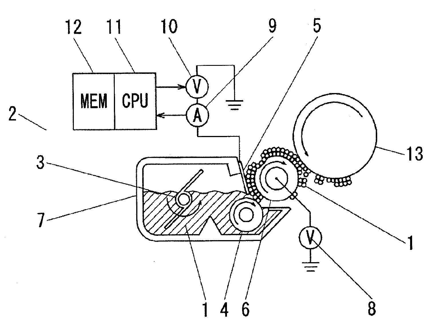
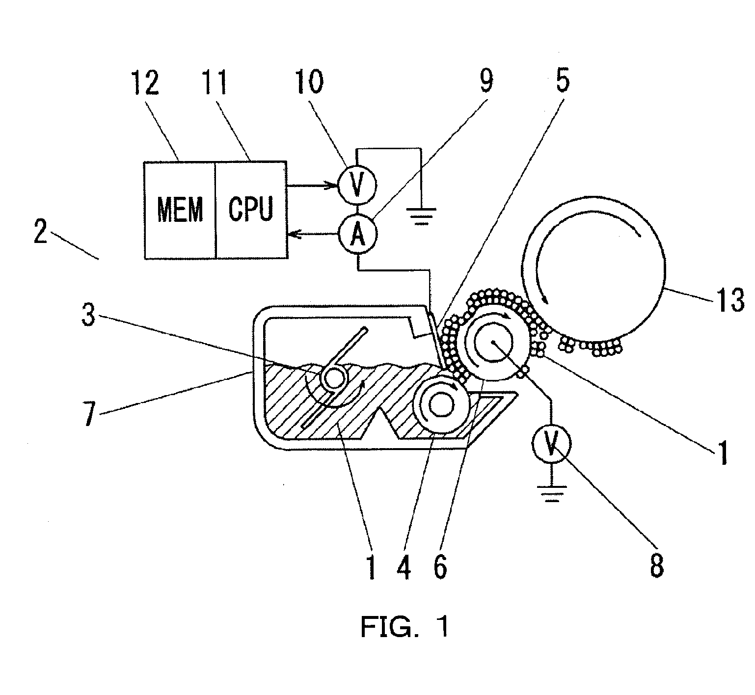
[0055]FIG. 1 is a sectional view illustrating a schematic structure of the developing apparatus in the first embodiment. FIG. 2 is a sectional view illustrating the schematic structure of the image forming apparatus in the first embodiment.

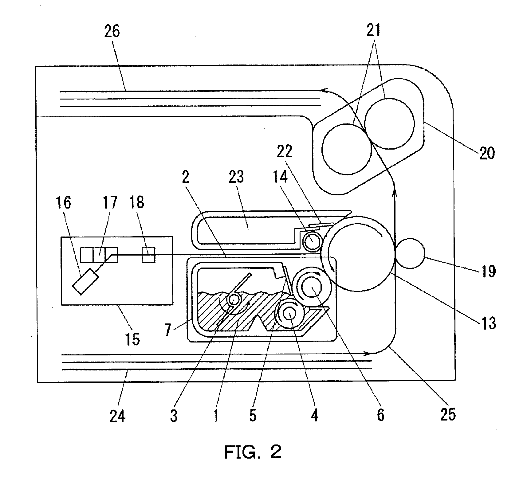
[0056]The overall structure of the image forming apparatus will be described with reference to FIG. 2.

[0057]As shown in FIG. 2, there are a charging roller 14, a laser scanner 15, a toner carrying member 6 serving as a rotatable developer carrying member, a transfer roller 19, and a cleaning member 22, arranged around an image bearing member 13. A conveying path of a recording material is formed so as to pass between the i...

second embodiment

[0107]A second embodiment according to the present invention will be described below. The components different from those in the first embodiment will he described, and the components same as those in the first embodiment will not be repeated.

[0108]FIG. 12 is a view showing a schematic structure of a developing apparatus in the present embodiment. FIG. 13 is a graph showing the relationship between the current flowing through the regulating member 5 and the rotational angle of the toner carrying member 6 in the present embodiment.

[0109]As shown in FIG. 12, a phase measuring device 27, serving as phase detecting means (phase detecting unit), that measures the rotational phase of the toner carrying member 6 is provided with the developing apparatus 2 in addition to the structure shown in the first embodiment. The phase measuring device 27 is connected to the operation unit 11. In the present embodiment, a rotary encoder that outputs a rotational angle of the toner carrying member 6 is...

third embodiment

[0113]A third embodiment according to the present invention will be described below. The components different from those in the embodiments 1 and 2 will be described, and the components same as those in the embodiments 1 and 2 will not be repeated.

[0114]FIG. 14 is a view showing a schematic structure of a developing apparatus according to the present embodiment.

[0115]In the present embodiment, the amperemeter connected to the regulating member 5 is not provided to the developing apparatus in the first embodiment, but a displacement measuring device 28 serving as deformation detecting means and a phase measuring device 27 that measures the rotational angle of the toner carrying member 6 are provided to the developing apparatus in the first embodiment as shown in FIG. 14. The contact portion between the toner carrying member 6 and the image bearing member 13 is present at the position at an angle of 145 degrees in the rotating direction of the toner carrying member 6 with the contact ...


PUM


Abstract

A developing apparatus includes a developer carrying member rotatably provided for carrying a developer; a regulating member that has conductivity, and is provided to be capable of being in contact with the developer carrying member for regulating a amount of the developer carried by the developer carrying member; a power supply that applies voltage to the regulating member; a deformation detecting unit that detects information relating to the deformation of the developer carrying member; and a control unit that controls the power supply to apply a correction voltage when a deformed portion of the developer carrying member passes through the regulating member in order that the amount of the developer carried by the developer carrying member in the circumferential direction is in uniform based on a result of the detection by the deformation detecting unit.

Description

BACKGROUND OF THE INVENTION[0001]1. Field of the Invention[0002]The present invention relates to a developing apparatus used for an image forming apparatus, such as a copier or a printer, having a function of forming an image onto a recording material such as a sheet.[0003]2. Description of the Related Art[0004]An image forming process of an image forming apparatus of a dry one-component electrophotographic system employing a contact developing system will be described with reference to FIG. 19.[0005]Toner (developer) 101 in a developing container 107 of a developing apparatus 102 is carried to a toner carrying member 106, serving as a developer carrying member, by a stirring member 103 and a supplying roller 104. The toner 101 is brought into sliding contact with the contact portion between the toner carrying member 106 and the supplying roller 104 so as to be deposited onto the toner carrying member 106. The deposited toner passes through the contact portion between a regulating m...

Claims


Application Information

Patent Timeline
Patent Type & Authority Applications(United States)
IPC IPC(8): G03G15/08
CPCG03G15/0812G03G2215/0634G03G15/0818
Inventor TANAKA, TAKAYUKI
Owner CANON KK
Why Eureka
Try Eureka