Sensor isolation plane for planer elements

a technology of planer elements and isolation planes, applied in the field of sensor isolation planes for planer elements, can solve the problems of only operative ion collection functions, shorten heater lifetime, and miss the opportunity to capture ions, so as to improve the operation of ionic collection and prevent ionic buildup , the effect of high electrical potential differen

Active Publication Date: 2009-10-15
DELPHI TECH IP LTD
View PDF2 Cites 18 Cited by
  • Summary
  • Abstract
  • Description
  • Claims
  • Application Information

AI Technical Summary

Benefits of technology

[0003]Other known prior art utilized a collector member that was connected to the negative terminal of the resistive heater. This was suggested at least as early as 1985, as disclosed in U.S. Pat. No. 4,733,056, and has more recently been commercialized, for instance in many current production motor vehicles employing a planar oxygen sensor provided by Delphi Automotive Systems and identified as the OSP+. In arrangements where the collector member is connected to the heater terminal, and when the heater is turned OFF, there is no electrical field between the collector element and the heater. When OFF no current flows through the heater and there is no potential drop along the length of the heater. Also, in typical implementations where the heater control involves electrically disconnecting the heater from ground to turn the heater OFF, the entire heater goes positive when turned OFF because of the connection of the positive lead to the power supply, but so does the collector member. As a result, the ion collection function is only operative when the heater is operating. This arrangement misses the opportunity to capture ions when the heater is not ON. The substrate typically starts out cold, thus creating a condition that is not conducive to ionic migration through the substrate. Because the ions in the substrate are more mobile at higher temperatures, they are most mobile when the heater is ON and then adjacent to the heater element. Also, because there is a voltage gradient along the length of a resistance heater when in operation, the ions tend to follow the electrical field along the direction where they have the greatest mobility. The higher temperatures along the heater, combined with the electrical field gradient along the length of the heater causes ions to migrate toward the negative terminal of the heater. This ion collection at the negative heater terminal shortens heater lifetime by physically forcing the heater terminal away from the heater leads, causing the connection to the conductive heater leads to be broken. This physical force is due to the physical presence of the ions gathering between the negative heater terminal and its lead.
[0004]It has now been discovered that in order to prevent ionic buildup near a terminal of a planar electrical resistance heater (a buildup that can damage the heater and break the electrical connection between the heater and its conductive lead), an ion collector can be employed near the heater to continuously attract the ions. An electrical field is established between the heater and the ion collector attracting the mobile ions toward the ion collector and repelling them away from the heater. To improve the operation of the ionic collection, the collector member is maintained at its attracting potential even when the heater is OFF or is operating at less than full power. Also, the heater is connected so as to establish a high electrical potential difference relative to the ion collector when the heater is OFF repelling the ions from the heater element and toward the ion collector. A heater control mechanism is employed to turn the heater on / off as desired and to regulate the voltage supplied to the heater if it is desired to operate the heater at less than full power. Preferably, the heater control is located between the negative heater terminal and ground.BRIEF DESCRIPTION OF THE DRAWINGS

Problems solved by technology

As a result, the ion collection function is only operative when the heater is operating.
This arrangement misses the opportunity to capture ions when the heater is not ON.
This ion collection at the negative heater terminal shortens heater lifetime by physically forcing the heater terminal away from the heater leads, causing the connection to the conductive heater leads to be broken.

Method used


Image

  • Sensor isolation plane for planer elements
  • Sensor isolation plane for planer elements
  • Sensor isolation plane for planer elements

Examples


Embodiment Construction

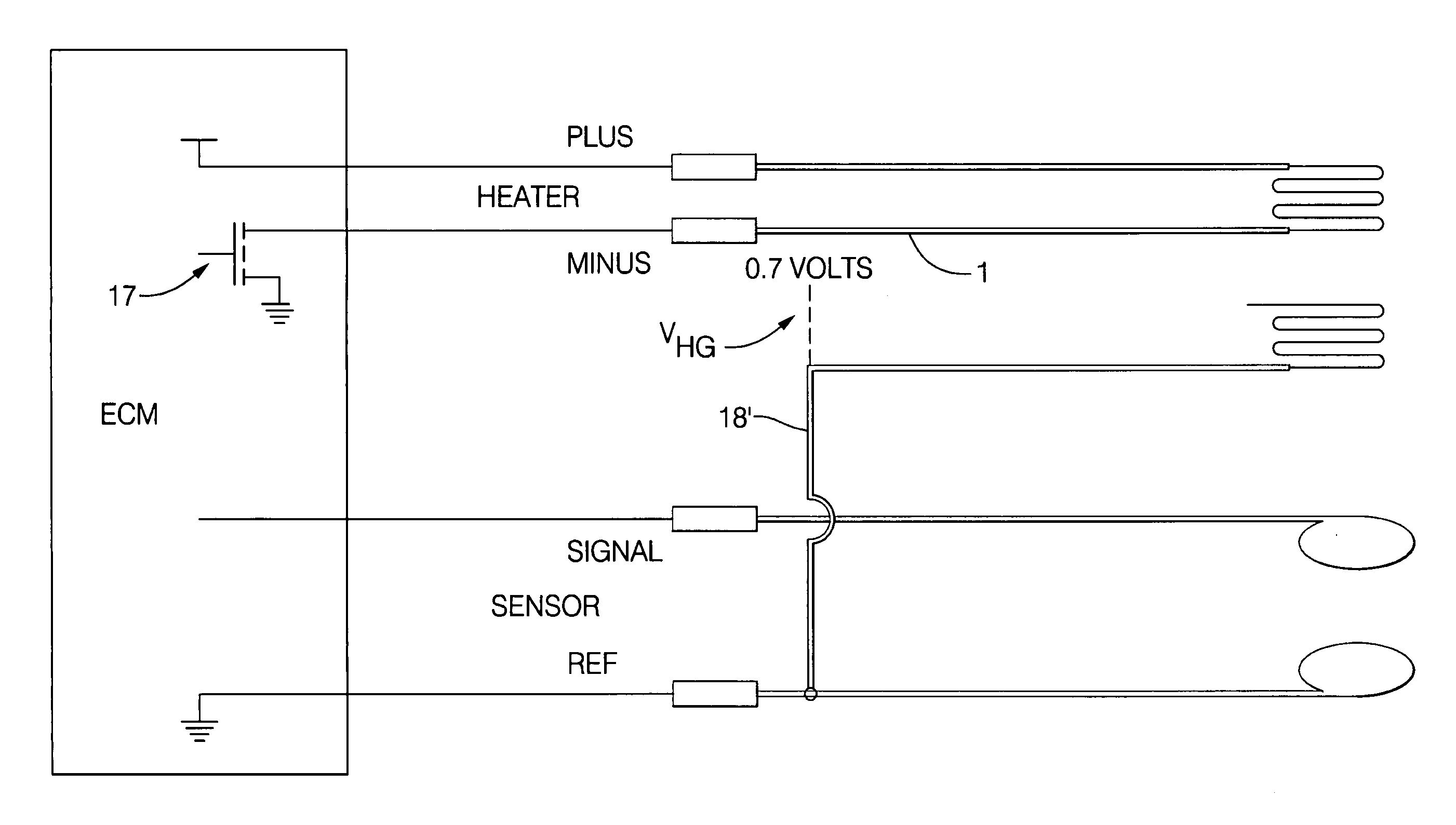
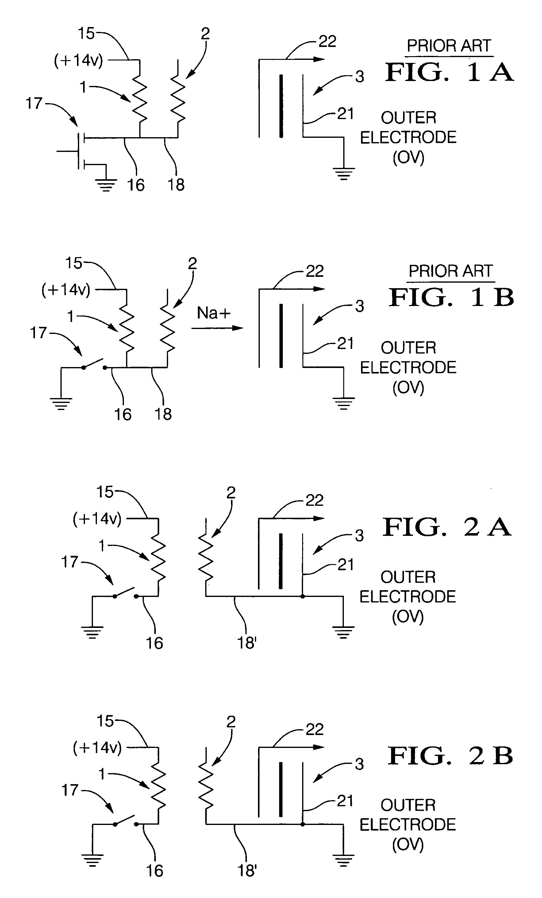
[0010]FIGS. 1a and 1b illustrate a prior art arrangement that has an electrical connection between the heater element 1 and the ion collector 2. As shown in FIG. 1a, when the heater is ON, the positive lead 15 of heater element 1 is connected to the positive supply, typically 14 volts, and the negative lead 16 is connected to the negative supply by heater control circuit 17. When the heater is ON, as shown in FIG. 1a, there is a strong electrical field in the vicinity of the positive connection while there is a weaker electrical field nearer to the negative terminal. The voltage drop along the length of the resistive heater causes the difference in field strength. Near the negative terminal, the field may be negligible because both the ion collector and the conductive lead are at approximately the same potential. Typically, because of the diode drop associated with the switching control circuit 17, the negative heater terminal stays slightly above system ground, perhaps by 0.7 volts...


PUM


Abstract

Elimination of sodium contamination at the negative terminal of an electrical stri resistance heater (1, FIGS. 2 and 4) for a gas sensor (3) can be accomplished by providing a grounding plane (-18′) electrically connected to system ground and located between the heater (1) and the sensor (3).

Description

FIELD OF THE INVENTION[0001]The present invention relates to a structure suitable for extending the useful lifetime of an electrical resistance heater employed for heating an ion-containing substrate.BACKGROUND AND SUMMARY OF THE INVENTION[0002]It was recognized at least as early as 1969 that a planar resistor was exposed to shortened lifetime if sodium ions were permitted to collect in the vicinity of the negative terminal of the resistor. U.S. Pat. No. 3,598,956 identified this problem and proposed a solution including providing a conductive barrier that could optionally be electrically biased relative to the resistors.[0003]Other known prior art utilized a collector member that was connected to the negative terminal of the resistive heater. This was suggested at least as early as 1985, as disclosed in U.S. Pat. No. 4,733,056, and has more recently been commercialized, for instance in many current production motor vehicles employing a planar oxygen sensor provided by Delphi Automo...

Claims


Application Information

Patent Timeline
Patent Type & Authority Applications(United States)
IPC IPC(8): F23Q7/22
CPCH05B3/03
Inventor KATTERMAN, JAMES A.WALLACE, II, DAVID P.WALLACE, SR., DAVID P.WALLACE, LINDA L.
Owner DELPHI TECH IP LTD
Why Eureka
Try Eureka