Ultra-violet sponge holder

a sponge holder and ultraviolet light technology, applied in the field of ultraviolet light emitting sterilization devices, can solve the problems of time-consuming, and achieve the effects of increasing the sterility of the sponge, and reducing the risk of contamination

Inactive Publication Date: 2009-10-15
THIRUPPATHI DEVARAJ
View PDF3 Cites 18 Cited by
  • Summary
  • Abstract
  • Description
  • Claims
  • Application Information

AI Technical Summary

Benefits of technology

[0005]The ultra-violet sponge holder is in the form of a container having a holder top containing the housing for the ultra-violet light source and a holder bottom containing the power source, the sponge holder and the drainage retention area. The housing containing the ultra-violet light source is located on the holder top and is held by a ultra-violet socket allowing for sterilization of sponge without damaging the ultra-violet light source from the drainage from the kitchen sponge. The drainage from the kitchen sponge is retained in the drainage retention area, which is also sterilized by the ultra-violet light and can be drained out at a later time. The ultra-violet light source is automatically activated for a short period of time when a on / off / auto switch is moved to the “auto” position causing the ultra-violet light to activate when the holder top is opened and then closed allowing for ample time for the sterilization of the kitchen sponge placed on the sponge holder. The ultra-violet sponge holder contains a reflective top coating and a reflective bottom coating on the inside of container allowing for a larger sterilization area of sponge by reflecting the ultra-violet light. The ultra-violet light source can also be turned on by moving the on / off / auto switch to the “on” position for a longer exposure of the sponge to the ultra-violet light and then turned off by either moving the on / off / auto switch to the “auto” position, which has a predetermined timing of turning on and off the ultra-violet light when the holder top is opened and closed, or moving the switch to the “off” position to turn the ultra-violet light off. The ultra-violet light source is powered by a battery source, which is a rechargeable battery located on the holder bottom and also having a rechargeable site to charge the battery by plugging into an outlet if one is available. The ultra-violet sponge holder can also have a removable sponge holder, which can be removed from the ultra-violet sponge holder containing a sponge holder drainage openings, which allows for drainage of liquids from sponge, in which not only sponges can be placed within the ultra-violet sponge holder to be sterilized but other items as well such as utensils and wash rags. The ultra-violet sponge holder can also have a holder bottom drainage openings to allow the liquid which is drained from the sponge to the drainage retention area to be drained away for the ultra-violet sponge holder. Multiple ultra-violet lights can be added to increase the sterility of the sponge such as adding a bottom ultra-violet light to the holder bottom allowing the sponge to be radiated by ultra-violet light from both side.
[0006]The ultra-violet sponge holder can also be utilized in the form of a hand held sterilization device to clean kitchen countertops and the like. The holder top contains a holder top window, which can be opened and closed to expose the ultra-violet light source to the external environment to sterilize other areas of the kitchen or house. Unplugging the power cord from the ultra-violet sponge holder and holding the ergonomic base of the holder bottom allows the ultra-violet sponge holder to be mobile and moving the on / off / auto switch to the “no” position activates the ultra-violet light to begin sterilization of other surfaces exterior to the ultra-violet sponge holder and moving the on / of / auto switch to the “off” position turns the ultra-violet light off.

Problems solved by technology

At present the kitchen sponges are disinfected by way of the microwave oven, which is hazardous to the sponge and by way of submerging the sponge in a bleach solution, which is time consuming.

Method used


Image

  • Ultra-violet sponge holder
  • Ultra-violet sponge holder
  • Ultra-violet sponge holder

Examples


Embodiment Construction

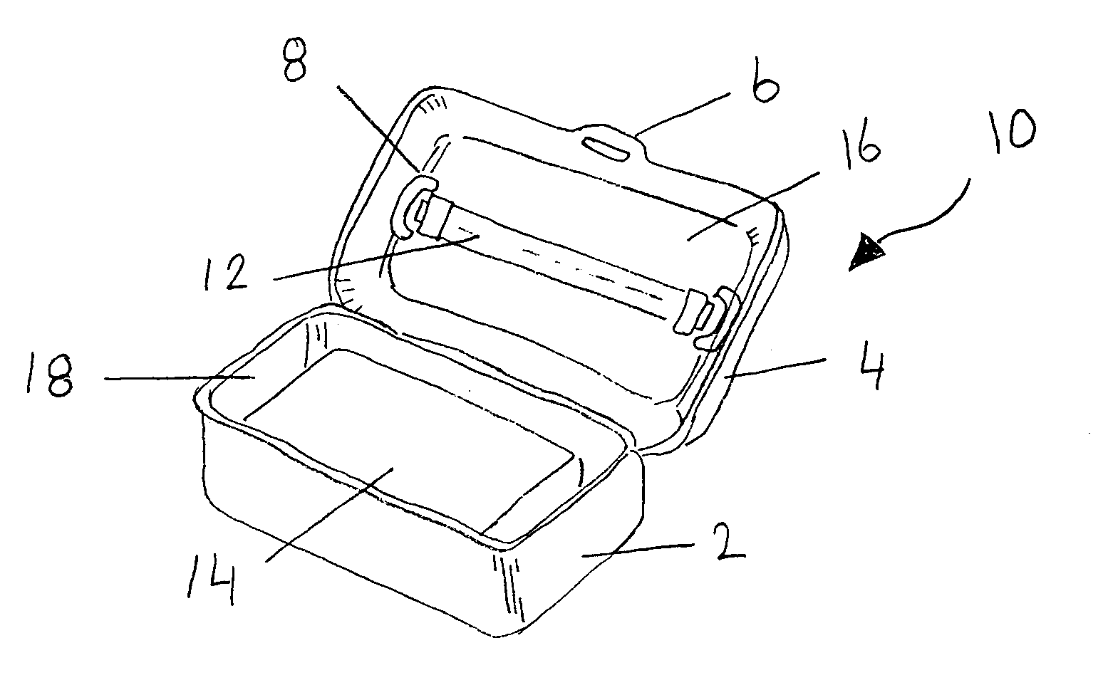
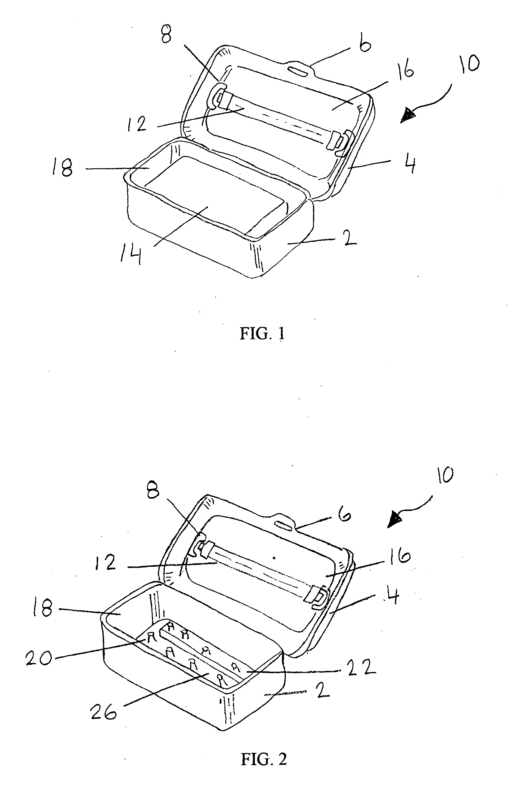
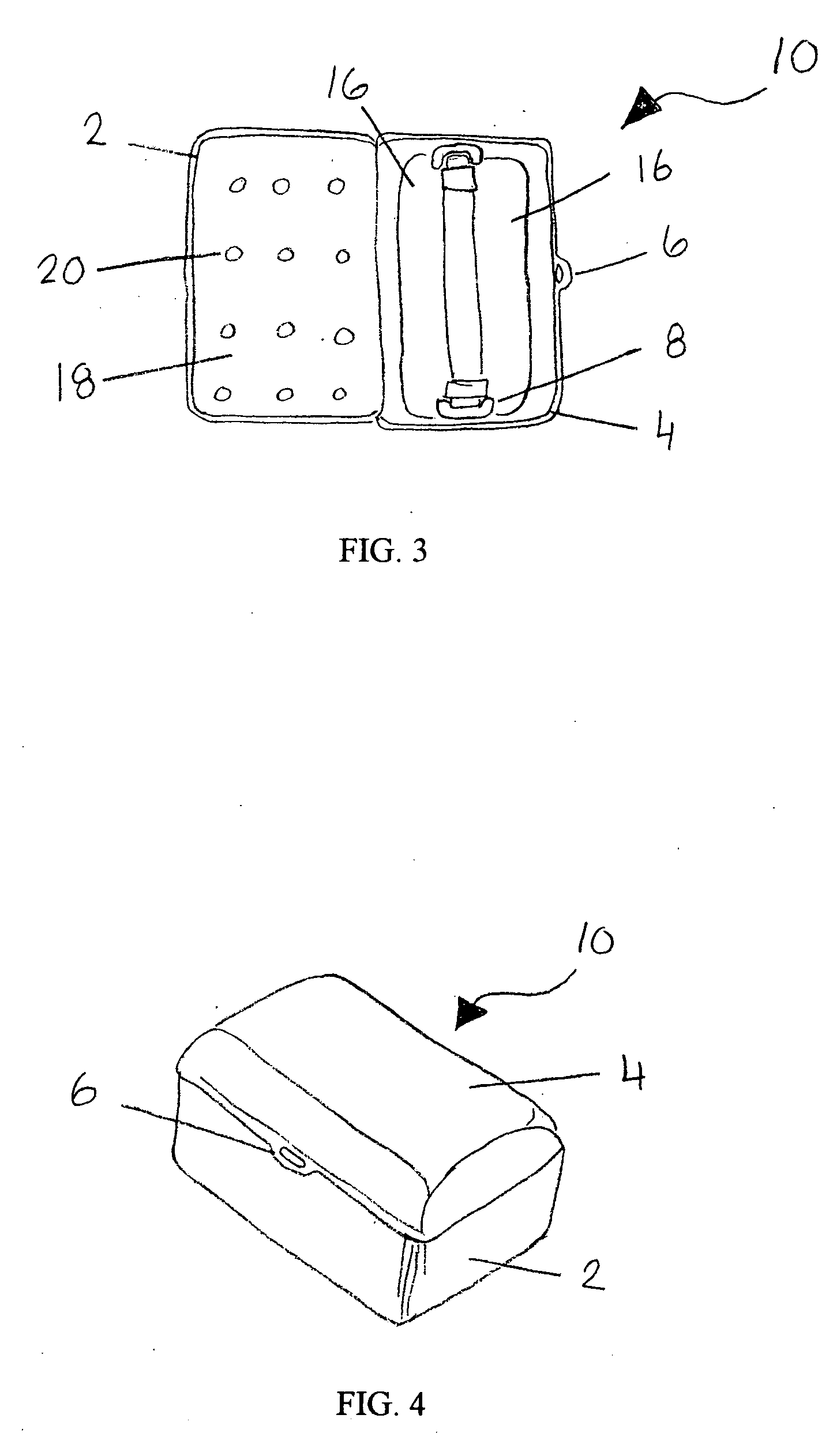
[0022]Referring now to the drawings wherein the depictions are for purposes of illustrating a preferred embodiment of the present invention only and not for the purpose of limiting the same. FIG. 1 is a plan view of a ultra-violet sponge holder 10 of present invention. FIG. 1 depicts the ultra-violet sponge holder 10 with a holder top 4 open exposing a sponge 14. The holder top 4 contains a ultra-violet light 12 which is being held in a ultra-violet socket 8 which through a electrical process aid in the illumination of ultra-violet light 12. There is a reflective top coating 16 and a reflective bottom coating 18 which helps radiate the sponge 14 located in a holder bottom 2 when the ultra-violet light 12 is illuminated. FIG. 2 is a plane view of ultra-violet sponge holder 10 without sponge 14, exposing a sponge holder 20 on which sponge 14 sits. The holder bottom 2 contains a drainage retention area 26 where the liquid from the sponge 14 sitting on sponge holder 20 drains into. FIG....


PUM

PropertyMeasurementUnit
wavelengthsaaaaaaaaaa
wavelengthaaaaaaaaaa

Abstract

A ultra-violet sponge holder that emits sufficient radiation to eradicate germs, bacteria, viruses and other pathogens and microorganisms on a kitchen sponge with a ultra-violet light located on a holder top which is powered by a rechargeable battery with a on/off/auto switch with a safety mechanism whereby only turning the ultra-violet light on when the holder top is closed, also the holder top contains a holder top window whereby allowing the ultra-violet sponge holder to be mobile and a holder bottom contains a sponge holder and a drainage retention area where liquid from sponge is collected.

Description

FIELD OF THE INVENTION[0001]The invention relates generally to a ultra-violet emitting sterilization device used to disinfect kitchen dishwashing sponges.BACKGROUND OF THE INVENTION[0002]Kitchen sponges are the number 1 source of germs in the house and are responsible for as many as 80 million Americans contacting food-borne illnesses each year and of those 9,000 die. Ultra-violet radiation is well known to killing germs and viruses in the radiation range of 300-200 nanometers short wavelengths. Ultra-violet lamps have been used to eradicate germs, purifying air, water and surfaces. The intensity of the radiation and duration of exposure determines the potency of the ultra-violet radiation. The shorter the wavelength the stronger and quicker the kill factor. Ultra-violet light with wavelength shorter than 300 nanometer is extremely effective in killing microorganisms. The most effective sterilizing range of UV is within the C bandwidth of 253.7 nm. This range is called germicidal UV...

Claims


Application Information

Patent Timeline
Patent Type & Authority Applications(United States)
IPC IPC(8): A61L2/10
CPCA61L2/10
Inventor THIRUPPATHI, DEVARAJ
Owner THIRUPPATHI DEVARAJ
Why Eureka
Try Eureka