Vehicle lamp

a technology for lamps and vehicles, applied in semiconductor devices for light sources, lighting and heating apparatus, transportation and packaging, etc., can solve problems such as difficult integral casting of 3 parts, projector lens disclosure, and insufficient illumination

Inactive Publication Date: 2009-10-15
STANLEY ELECTRIC CO LTD
View PDF12 Cites 94 Cited by
  • Summary
  • Abstract
  • Description
  • Claims
  • Application Information

AI Technical Summary

Benefits of technology

[0030]In the above-described vehicle lamp including the projector headlight, the vehicle lamp can include a headlight for a high beam and other lamp such as a position lamp and the like because the projector headlight can be designed to fit in a small space. When the vehicle lamp is composed of the projector headlight(s) using LED light source(s) for both a high beam and a low beam, the vehicle lamp can provide a favorable light distribution with nearly the same color tone between a high beam and a low beam.

Problems solved by technology

Thus, the above-described structure may include a problem in that the chromatic aberration causes an unclear cut-off line CL80 in the light distribution pattern P50 shown in FIG. 7(B).
In this case, because the LED light source may include more light emission points (i.e., blue light LEDs with wavelength conversion layer(s)) as compared with a normal incandescent or other single light source bulb, the LED light source may cause a problem such as projecting blue light near the cut-off line CL80 while widely refracting light at the edge portion of the projector lens.
Consequently, the projector lens disclosed in patent document No. 1 and the shade disclosed in patent document No. 2 may not adequately solve the above-described problems in the vehicle headlight using the LED light source.
The projector lens disclosed in patent document No. 3 may be difficult to integrally cast while maintaining the accuracy thereof so as to conform a light distribution standard for a headlight.
In addition, the projector lens may cause problems such that a shape thereof becomes thick, and therefore the projector may cause the projector headlight to become high cost and a decrease of the brightness.

Method used


Image

  • Vehicle lamp
  • Vehicle lamp
  • Vehicle lamp

Examples


Embodiment Construction

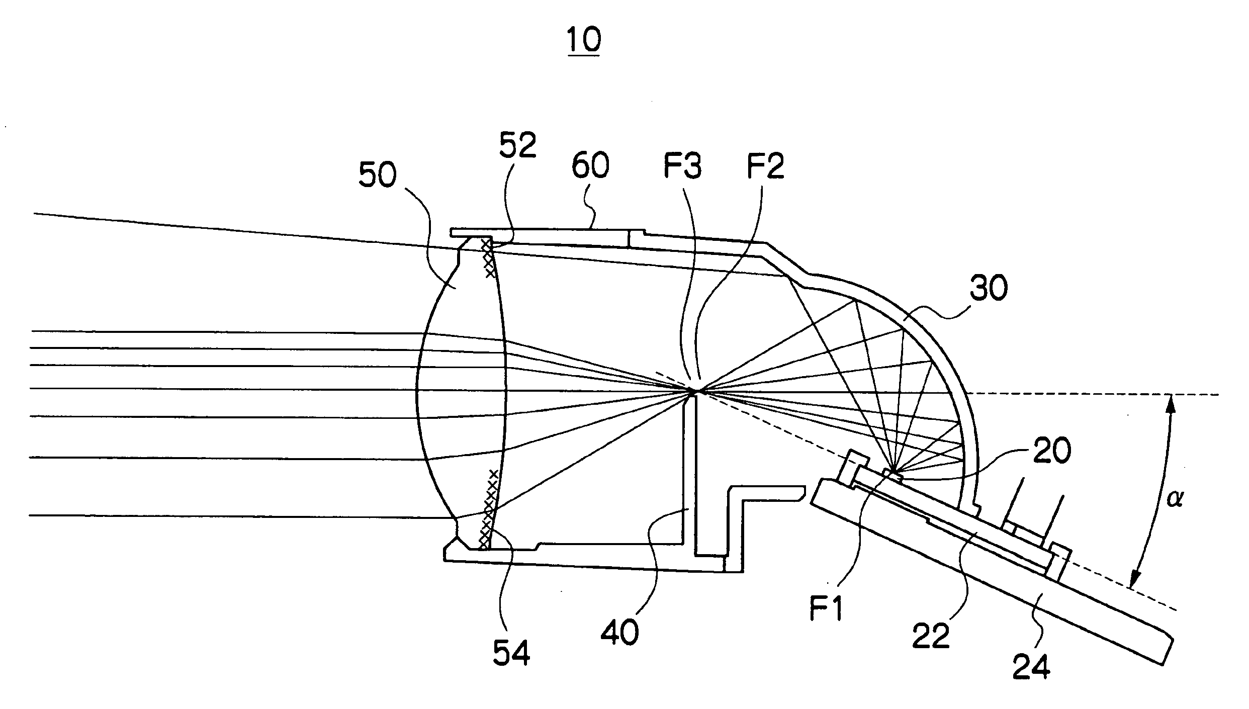
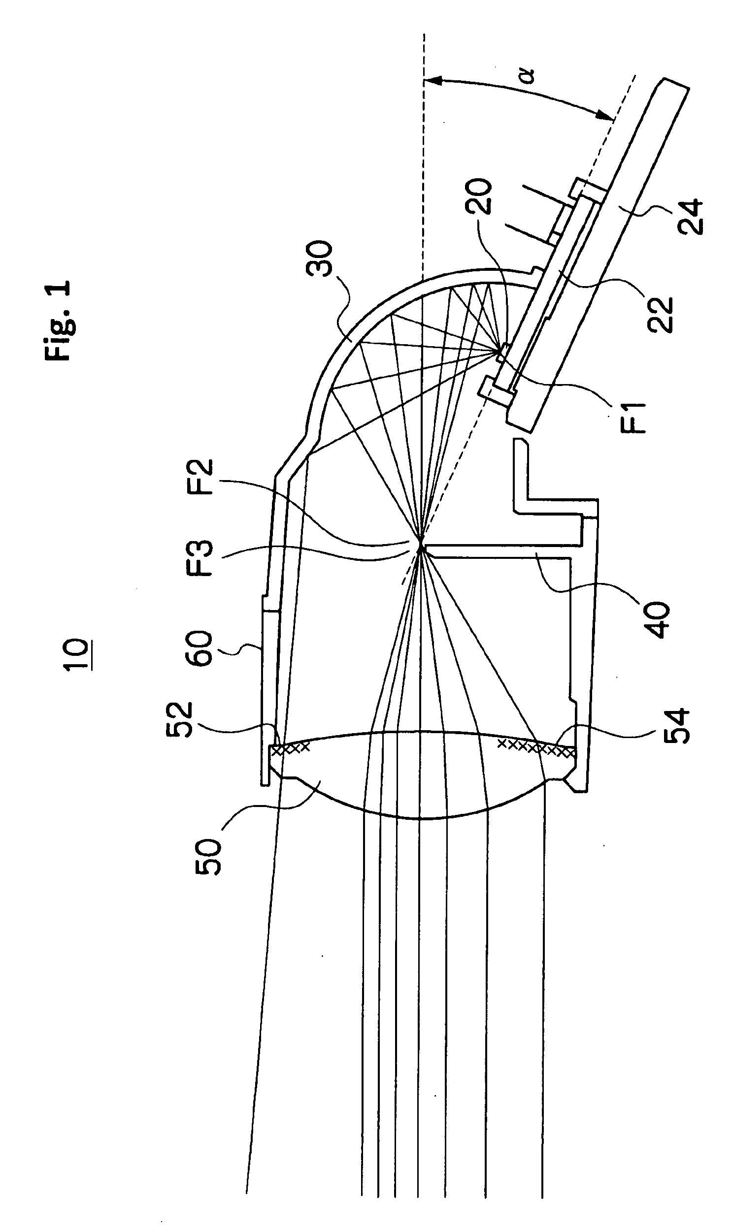
[0039]The disclosed subject matter will now be described in detail with reference to FIGS. 1 to 6. FIG. 1 is a schematic cross-section view showing an exemplary embodiment of a low beam projector headlight made in accordance with principles of the disclosed subject matter.

[0040]The projector headlight 10 can include: an LED light source 20; a reflector 30 for reflecting light emitted from the LED light source 20; a shade 40 for shielding a part of the light reflected by the reflector 30; a projector lens 50 for projecting a light that is not shielded with the shade 40, where the projector lens 50 is composed of a convex lens having an optical axis and a focus F3 located on the optical axis; and a casing 60 for holding the projector lens 50.

[0041]The LED light source 20 can include at least one LED chip and can emit white light using a wavelength-conversion material. For example, the LED light source 20 can be composed of a blue LED chip and a yellow phosphor as the wavelength-conver...


PUM


Abstract

A vehicle lamp including a projector headlight using an LED light source for a low beam can include a shade, an LED light source, an ellipsoidal reflector and a projector lens. Both a focus of the projector lens and a top edge of the shade can be located near a second focus of the reflector. The LED light source can be located near a first focus located below the second focus of the reflector. Therefore, light emitted from the LED light source can be effectively gathered near the focus of the projector lens via the reflector and can be projected via the projector lens with high light use-efficiency. The projector lens can include light dispersing portions or structures on an upside and downside thereof for reducing chromatic aberration. Thus, the lamp can project a favorable light distribution that can conform to light distribution standards for vehicle headlights and the like.

Description

[0001]This application claims the priority benefit under 35 U.S.C. §119 of Japanese Patent Application No. 2008-041743 filed on Feb. 22, 2008, which is hereby incorporated in its entirety by reference.BACKGROUND[0002]1. Field[0003]The presently disclosed subject matter relates to a vehicle lamp including a projector headlight using an LED light source for a low beam, and more particularly to a vehicle lamp including a projector headlight having a favorable light distribution pattern that can conform to a light distribution standard for a headlight.[0004]2. Description of the Related Art[0005]A projector headlight for a low beam and / or a high beam is frequently incorporated into vehicle lamps, such as a headlamp, a position lamp, a turn-signal lamp, brake lamp, traffic lamp, etc. The projector headlight may allow a light-emitting area thereof to be reduced and therefore allows the vehicle lamp including the projector headlight to be minimized in comparison with other type headlights....

Claims


Application Information

Patent Timeline
Patent Type & Authority Applications(United States)
IPC IPC(8): B60Q1/00
CPCF21Y2101/02F21S48/1159F21Y2115/10F21S41/147F21S41/275
Inventor KOIKE, TERUO
Owner STANLEY ELECTRIC CO LTD
Why Eureka
Try Eureka