Terminal

a terminal and terminal technology, applied in the field of terminals, can solve the problems of insufficient bands, inability to establish a home network technology, and difficulty for general users to install ethernet cables in existing houses, etc., and achieve the effect of high transmission quality, high speed and optimal increase of multiple access transmission speed

Active Publication Date: 2009-10-15
PANASONIC CORP
View PDF88 Cites 37 Cited by
  • Summary
  • Abstract
  • Description
  • Claims
  • Application Information

AI Technical Summary

Benefits of technology

[0047]According to a control method and a terminal of the present invention, the speed of multiple access transmission by a high-frequency digital transmission can be optimally increased using a communication medium which is not intended for high frequency digital communication, such as an electric light wire, a wireless medium, a coaxial cable, a speaker line, an avionics line or the like.
[0048]By the conventional art, it was difficult to realize a system for distributing video, which is transmitted at a high communication speed and does not permit data loss, or audio, for which delay is strictly restricted, based on the IP multicast protocol or the IP broadcast protocol, using a communication medium not intended for high frequency digital communication.
[0049]According to the technology disclosed by the present application, multiple access transfer of the 1:n link with high transmission quality, high speed and high stability is realized even with a medium not intended for high frequency digital communication.
[0050]Accordingly, using the technology disclosed by the present application, a system for distributing video or audio using the IP multicast protocol or the IP broadcast protocol by a medium not intended for high frequency digital communication.

Problems solved by technology

However, there is no established technology for home network, which is at one end of the access lines.
However, it is difficult and costly for general users to newly install an Ethernet cable in an existing house.
However, these communication media are not intended for fast digital communication, and so have disadvantages that, for example, sufficient bands are not guaranteed or communication lines are not reliable.
However, the technique of increasing the speed by optimizing the modulation / demodulation format in the 1:1 link is not suitable to the transfer in the n:1 link.

Method used


Image

  • Terminal
  • Terminal
  • Terminal

Examples


first embodiment

[0155]In this embodiment, the present invention is applied to, for example, a network system constructed as a transmission / reception system usable for video distribution, audio distribution, web browsing, file transfer or the like in households, small offices or the like; a video or audio distribution system usable in large scale building structures; or an avionics system in transportation facilities or areas where a large number of people gather.

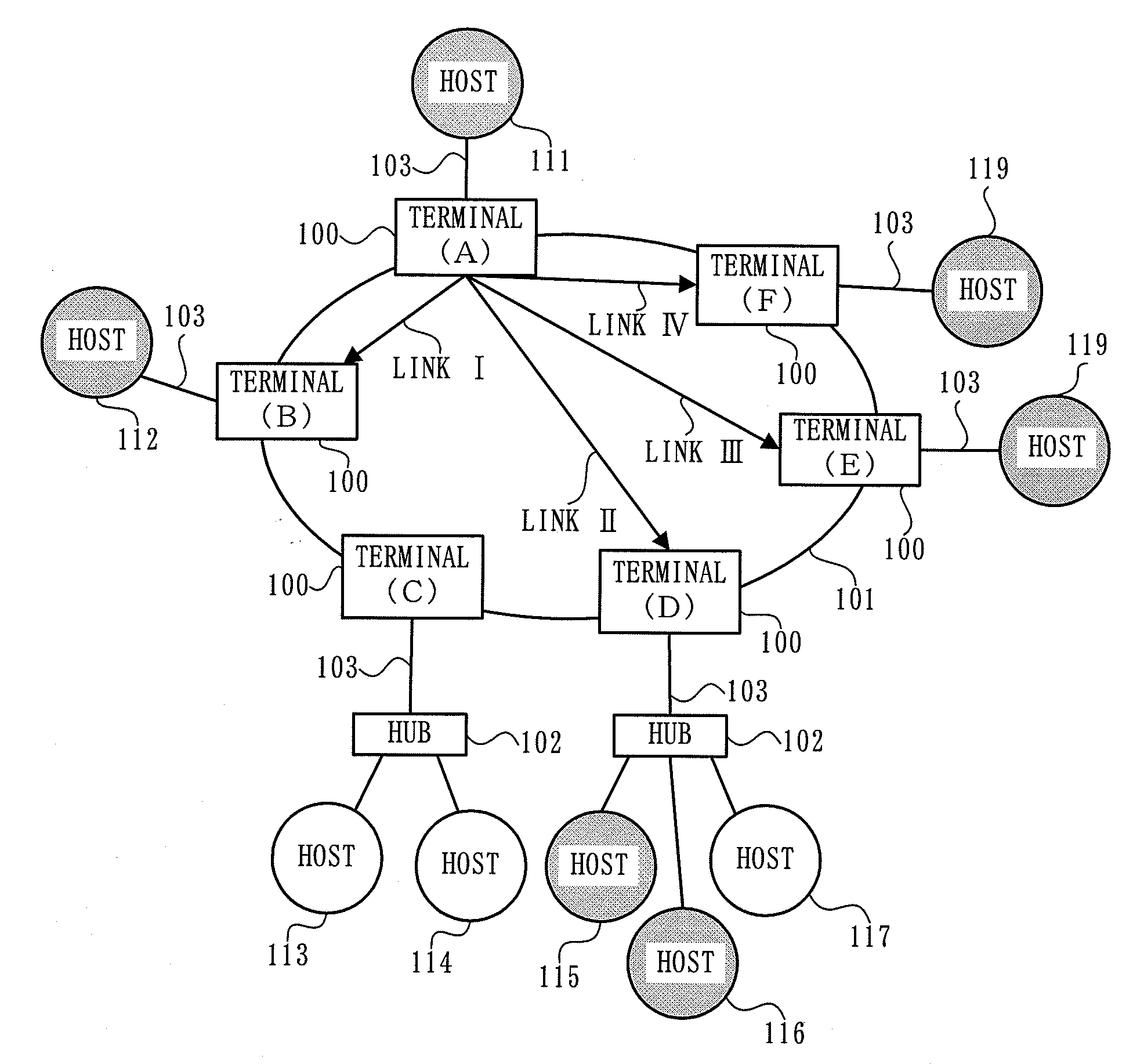
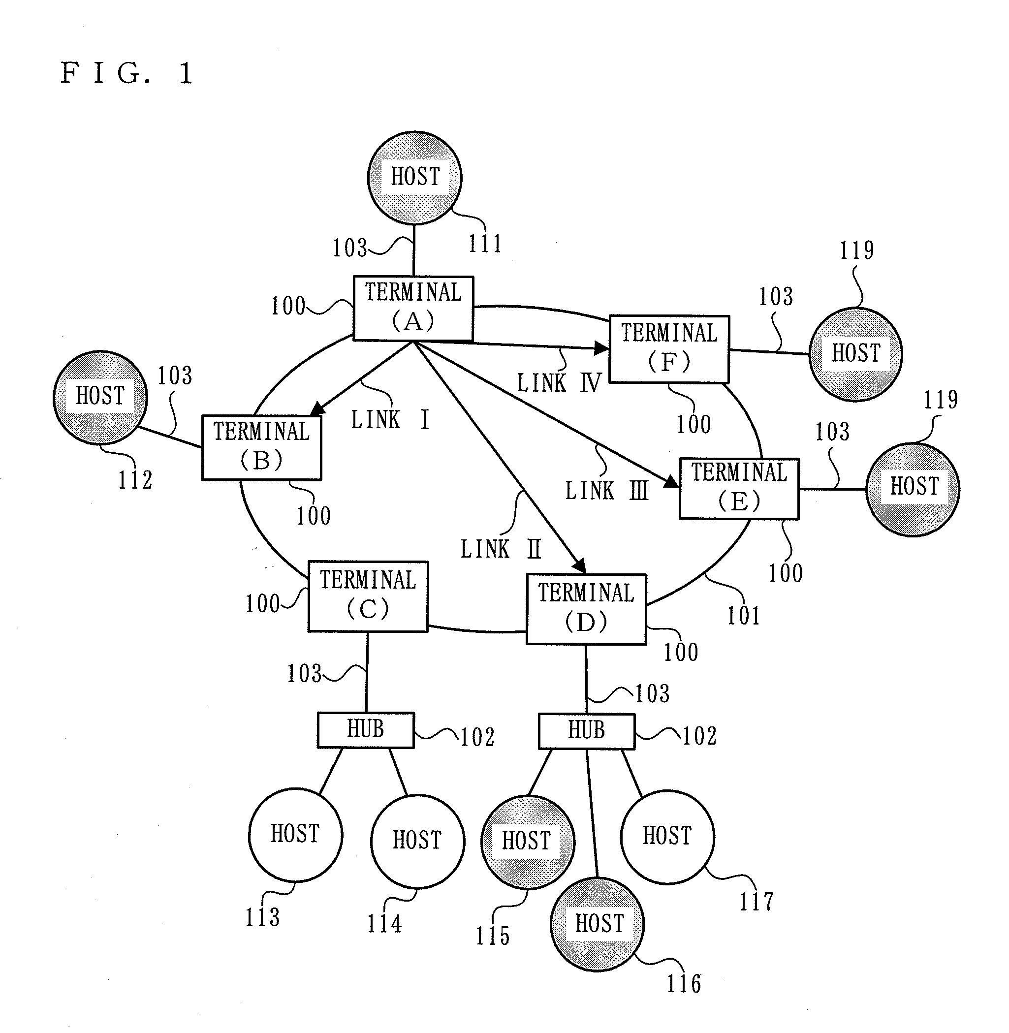
[0156]FIG. 1 shows an exemplary entire structure of a system using communication devices according to a first embodiment of the present invention. The communication system shown in FIG. 1 includes electric light wire communication terminals 100 (terminals (A) through (F)), an electric light wire sub network 101, layer 2 level hubs 102, networks 103, and hosts 111 through 119.

[0157]In the system shown in FIG. 1, nine IP hosts (hosts 111 through 119) having communication means conformed to the IP protocol used widely in general and having an ...

second embodiment

[0516]In a second embodiment, the speed of multiple access transmission is increased by a simpler method than in the first embodiment. The first embodiment is especially effective in a medium, such as an existing dedicated line or the like, which does not have much varied frequency characteristic on the transmission path.

[0517]The basic structure of a terminal 100 according to the second embodiment is the same as that according to the first embodiment. Thus, FIG. 1 through FIG. 3 are incorporated in this embodiment and the description of the structure will be repeated. As in the first embodiment, it is assumed that the network 103 is conformed to the Ethernet (registered trademark) standard. In the second embodiment, also as in the first embodiment, a multiple carrier transmission by DMT is performed in the network 101.

[0518]FIG. 16 shows a structure of group management information 1701 used by the terminal 100 in the second embodiment.

[0519]The group management information 1701 acc...

third embodiment

[0591]In a third embodiment, an exemplary communication terminal capable of increasing the speed of multiple access transmission by a simpler method than in the second embodiment will be described. The communication terminal according to this embodiment is especially effective in a communication medium, such as an existing dedicated communication medium or the like, which does not have much varied frequency characteristic on the transmission path.

[0592]FIG. 20 shows a structure of a terminal 1000 according to the third embodiment. The format of frames transmitted or received in the network 101 is the same as that in the first embodiment, and thus FIG. 3 is incorporated in this embodiment. In the third embodiment, the terminal 1000 performs a multiple carrier transmission by DMT in the network 101 as in the first embodiment.

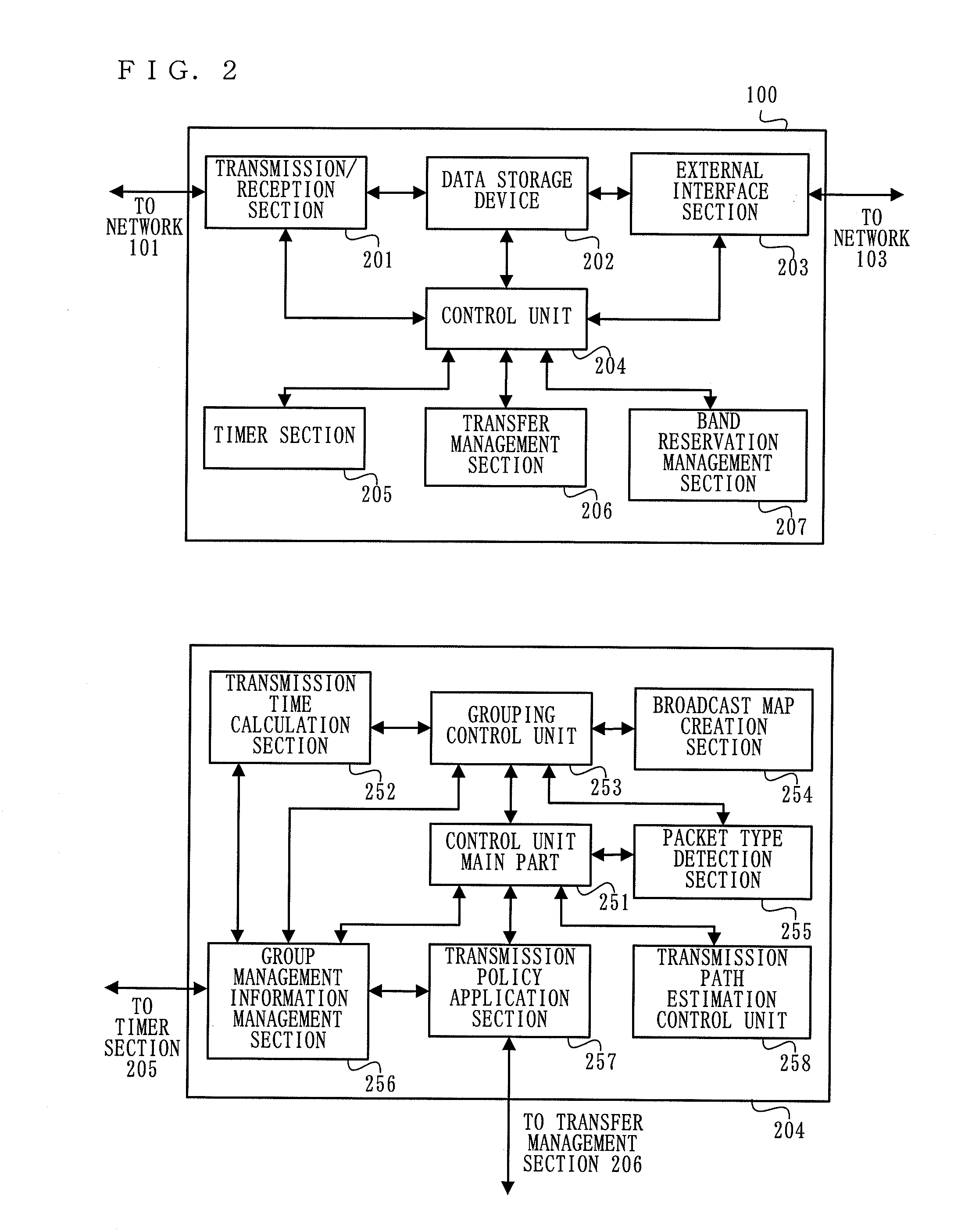
[0593]The terminal 1000 includes a transmission / reception section 2001, a data storage section 2002, an external interface section 2003, a control unit 2004, a ti...


PUM


Abstract

Provides a terminal for performing multiple access transmission suitable to a transmission path having varied characteristics. The terminal (100) includes a transmission / reception section (201), a control unit (204), a transfer management section (206), and an external interface section (203). The terminal (100) refers to an IGMP (MLD) message received by the transmission / reception section (201) to classify a transmitter host and a relay device of this message based on the characteristic of the transmission path, and performs a multiple access transmission of a multicast packet in a form suitable to the characteristic of the respective transmission path.

Description

TECHNICAL FIELD[0001]The present invention relates to a terminal, and more specifically, a terminal for performing media access control in communication control.BACKGROUND ART[0002]Currently, proper broadband access lines have been provided based on XDSL or FTTH technologies and access lines having a high transmission capability are spreading for household use.[0003]Therefore, high quality access lines can now be commonly used at home. However, there is no established technology for home network, which is at one end of the access lines.[0004]General users can construct a fast and high quality network in a household by installing a high frequency dedicated communication line such as Ethernet (registered trademark) or the like. However, it is difficult and costly for general users to newly install an Ethernet cable in an existing house.[0005]Obviously, it will be highly advantageous for these users to construct a fast digital network at low cost without installing a physical cable, if...

Claims


Application Information

Patent Timeline
Patent Type & Authority Applications(United States)
IPC IPC(8): H04L12/56H04L45/16
CPCH04L47/15H04L12/18H04B7/15542
Inventor YAMAGUCHI, TSUYOSHIIGATA, YUJIYOKOMITSU, YASUSHIYASUKAWA, TORUOHMI, SHINICHIROIKEDA, KOJIKATAOKA, MASANORIYANO, JUNJIKURODA, GO
Owner PANASONIC CORP
Why Eureka
Try Eureka