Mobile intelligent metering and charging system for charging uniquely identifiable chargeable vehicle destinations and method for employing same

a charging system and uniquely identifiable technology, applied in the direction of liquid/fluent solid measurement, process and machine control, electric devices, etc., can solve the problems of adding additional stress to an already overloaded power grid, reducing and increasing electric power costs during peak us

Inactive Publication Date: 2009-10-15
JUICE TECH
View PDF47 Cites 90 Cited by
  • Summary
  • Abstract
  • Description
  • Claims
  • Application Information

AI Technical Summary

Benefits of technology

[0007]In its most general configuration, the present invention advances the state of the art with a variety of new capabilities and overcomes many of the shortcomings of prior devices in new and novel ways. In its most general sense, the present invention overcomes the shortcomings and limitations of the prior art in any of a number of generally effective configurations. The instant invention demonstrates such capabilities and overcomes many of the shortcomings of prior methods in new and novel ways.

Problems solved by technology

This load is a concern to utility companies because it means that there will be increased load on the utility grid, which may add additional stress to an already overloaded power grid.
Traditionally, electric power is priced on a demand basis, resulting in higher electric power costs during peak use, which generally occurs in the daytime, and lower electric power costs during off-peak use, which generally occurs at night.
Additionally, shifting such power demands to night time use may help even out the demand for electrical power, when viewed from a 24 hour day perspective, which would tend to decrease the maximum system capacity needed.

Method used


Image

  • Mobile intelligent metering and charging system for charging uniquely identifiable chargeable vehicle destinations and method for employing same
  • Mobile intelligent metering and charging system for charging uniquely identifiable chargeable vehicle destinations and method for employing same
  • Mobile intelligent metering and charging system for charging uniquely identifiable chargeable vehicle destinations and method for employing same

Examples


example 2

Vehicle System Meter to AMI Smart Meter and Consumer Specific Data System

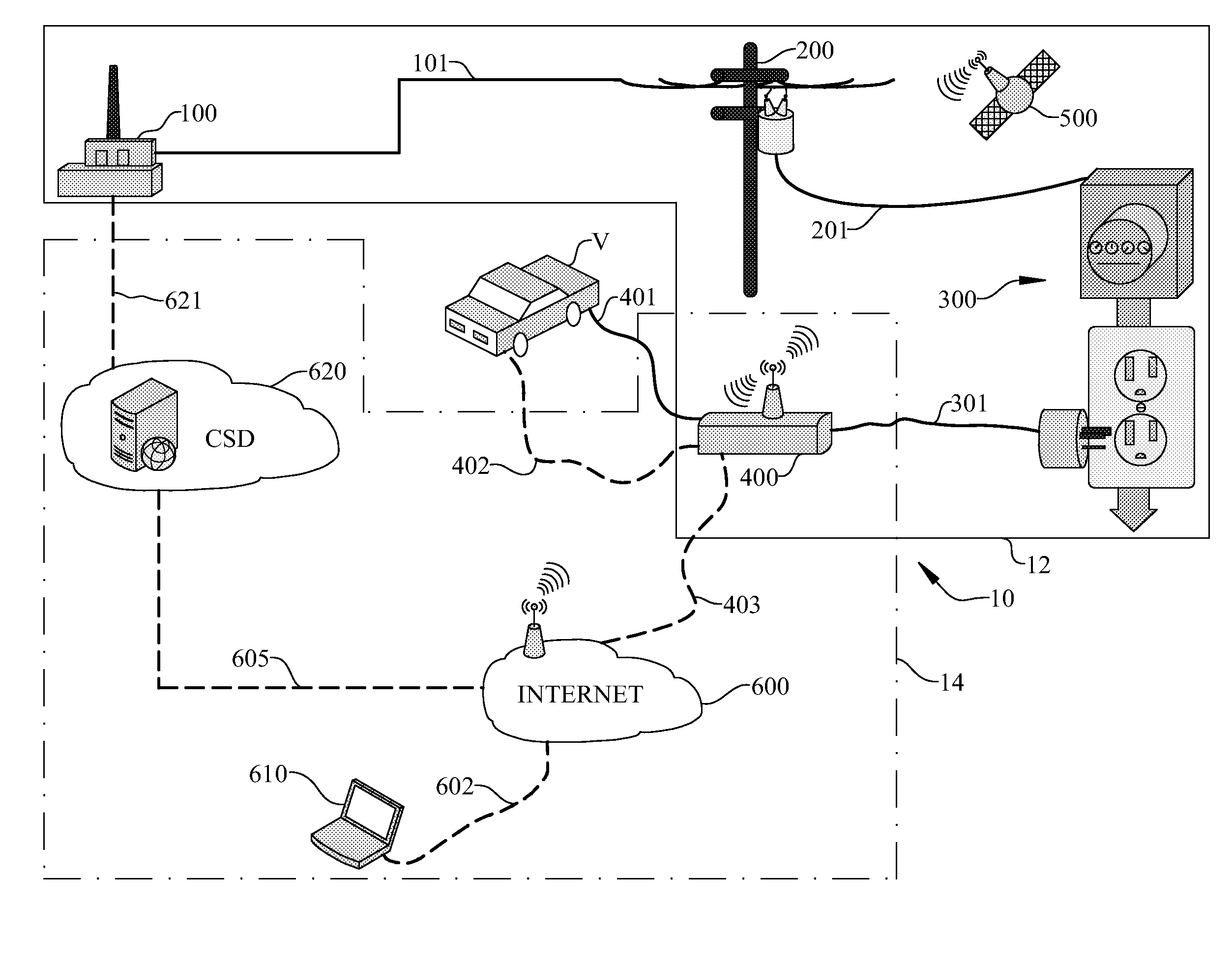
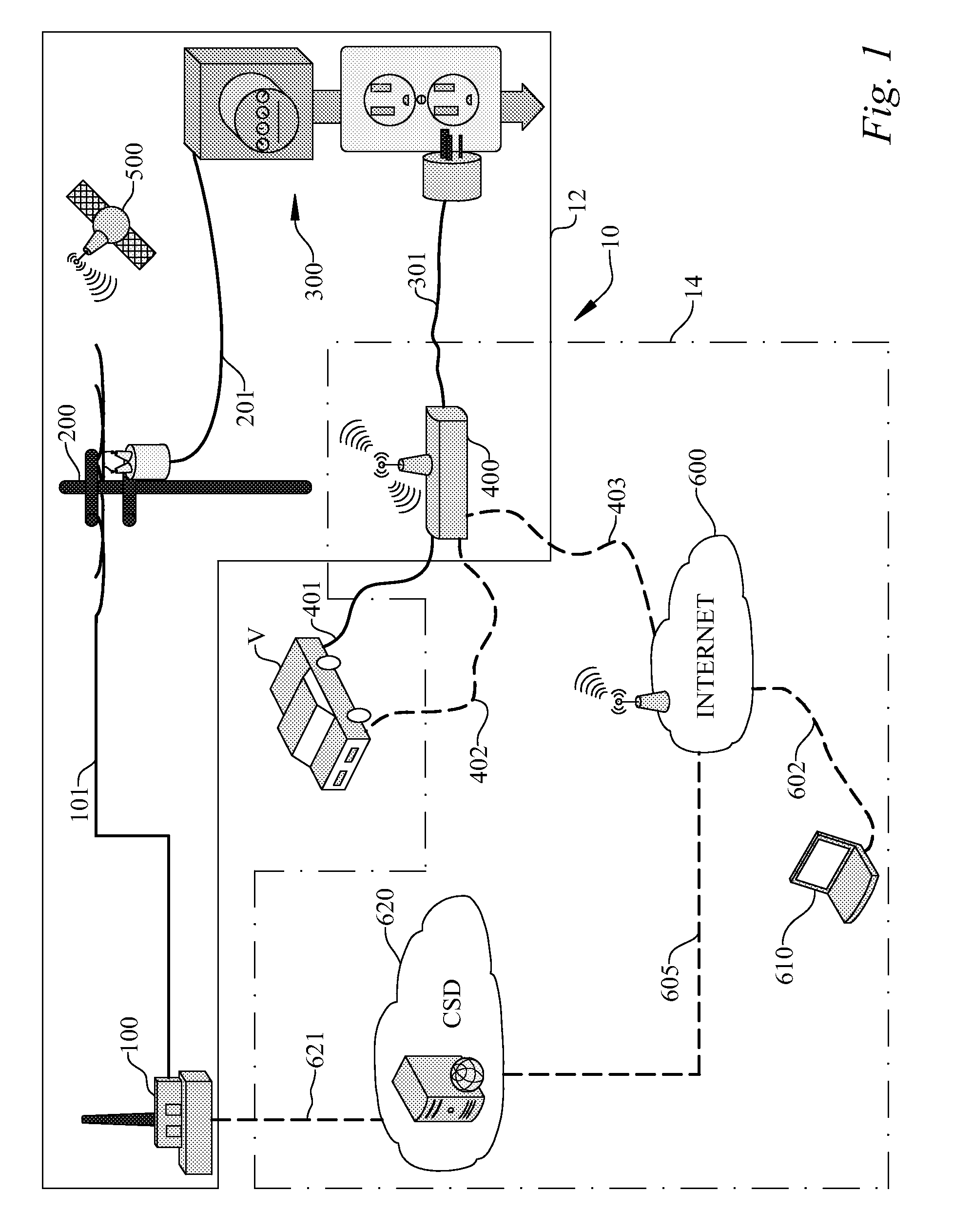
[0029]By way of identification only, AMI is an acronym for the term “Advanced Metering Infrastructure,” which is known in the art to represent a means, generally deployed by a utility company, to serve as an automated communication infrastructure that allows the utility direct access to a customer's meter and / or area / region. With this direct access, the utility is able to implement demand response programs and also give real-time pricing signals and energy consumption set points to homes and businesses. The AMI allows two-way communications between the utility company and the meter.

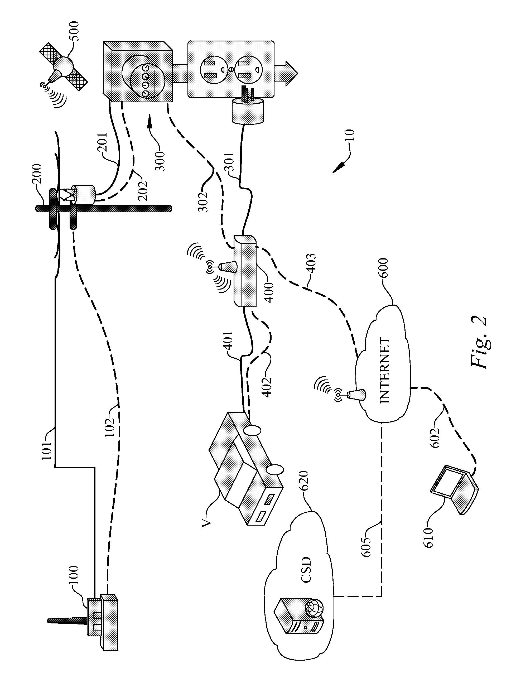
[0030]In this embodiment, seen illustrated in FIG. 2, the power distribution system limb (12) is similar to that as seen in Example 1, and the various structures may be exemplified as discussed above in Example 1. Electrical power flows from a power source (100), in this case a utility, through a power source—point of distribution po...

example 3

Vehicle System Meter to AMI UCM and Consumer Specific Data System

[0033]This embodiment illustrates a variation on the AMI system described in Example 2, and is seen illustrated in FIG. 3. The details of the power distribution system limb (12) remain unchanged. However, in the power consumption control and recordation limb (14) of the system (10), the vehicle system meter (400) communicates via AMI located on the point of distribution means (200) through a point of distribution—vehicle system meter communication link (203), rather than through the point of service—vehicle system meter communication link (302) and then to the point of distribution (200) by means of a point of distribution—point of service communication link (202) as previously described.

[0034]This embodiment describes a situation where the vehicle system meter (400), running an internet (600) enabled webserver that allows the owner of the vehicle system meter (400) to implement charging profiles and view statistics, c...

example 4

Vehicle System Meter to Mobile Metering Infrastructure (MMI) and Consumer Specific Data System

[0035]This embodiment, seen in FIG. 4, expands the flexibility of the system beyond that of Example 1, which contemplated a dedicated point of service (300) in the power transmission limb (10). In this embodiment, a mobile metering interface (MMI) allows charging anywhere the system (10) is configured for its use, without the need for any metering at the point of service (300). In addition, this embodiment illustrates the ability of the MMI system to detect and identify multiple power sources (110, 120, 130) and for the consumer specific data system (620) to differentiate and report to multiple power sources (110, 120, 130) based on such detection and identification.

[0036]As seen in FIG. 4, multiple power sources (110, 120, 130) transmit power via their respective power source—point of distribution power transmission links (101) through point of distribution (200) to multiple points of serv...


PUM


Abstract

The instant invention relates to a mobile intelligent metering and charging system for charging uniquely identifiable chargable vehicle destinations (V) and method for employing the same. The system includes at least a power distribution system limb and a power consumption control and recordation limb. A vehicle system meter and at least one programmable command and control system identify unique vehicles, batteries, user accounts or other predetermined locations for charging and accounting purposes. Both the at least one programmable command and control system and the vehicle system meter are in communication with both the power distribution system limb and the power consumption control and recordation limb, and the at least one programmable command and control system controls the transmission of power through the vehicle system meter according to a predetermined and programmable algorithm, resulting in charging of the uniquely identifiable chargable vehicle destination.

Description

RELATED APPLICATIONS[0001]This application claims the benefit of U.S. provisional patent application Ser. No. 61 / 123,701; filed Apr. 10, 2008; and U.S. provisional patent application Ser. No. 61 / 086,265; filed Aug. 5, 2008; all of which are incorporated by reference as if completely written herein.STATEMENT REGARDING FEDERALLY SPONSORED RESEARCH OR DEVELOPMENT[0002]This invention was not made as part of a federally sponsored research or development project.TECHNICAL FIELD[0003]The instant invention relates to a mobile intelligent metering and charging system for charging uniquely identifiable chargable vehicle destinations and a method for employing the same.BACKGROUND OF THE INVENTION[0004]With automotive manufacturer's plans to release electric vehicles and plug-in hybrid electric vehicles onto the streets, utility companies must plan for a significant load addition to the electric power grid. This load is a concern to utility companies because it means that there will be increase...

Claims


Application Information

Patent Timeline
Patent Type & Authority Applications(United States)
IPC IPC(8): G06F1/26G06F17/00
CPCB60L11/1818Y04S30/14B60L11/1838B60L11/184B60L11/1842B60L11/1846B60W10/26B60W20/00G06Q50/06Y02E60/721Y02T10/6269Y02T10/7005Y02T90/121Y02T90/128Y02T90/14Y02T90/16Y02T90/163Y02T90/169Y04S10/126B60L11/1824B60L2240/70Y02T10/7072B60L53/16B60L53/64B60L55/00B60L53/65B60L53/66B60L53/67B60L53/68B60L53/305Y02E60/00Y02T10/62Y02T10/70Y02T10/72Y02T90/12Y02T90/167B60W20/11
Inventor HOUSH, RICHARDYURKOVICH, BENJAMIN JOSEPH
Owner JUICE TECH
Why Eureka
Try Eureka