
Shielded connector and method of manufacturing shielded connector

a shielded connector and connector technology, applied in the field of shielded connectors, can solve the problems of difficult to concentrate the pressure in calking, the apparatus is constituted by a complex structure and expensive, and the shielded shell is difficult to be manufactured simply, so as to achieve stable integration and simple manufacturing

Active Publication Date: 2009-10-22
YAZAKI CORP
View PDF4 Cites 12 Cited by
  • Summary
  • Abstract
  • Description
  • Claims
  • Application Information

AI Technical Summary

Benefits of technology

The invention provides a shielded connector that can be easily manufactured, is cost-effective, and can be stably integrated. The connector includes a terminal-attached wire, a housing, a shielded shell, a knitted conductor, and a shield ring. The shielded shell is integrated with the housing and contains a calked portion that is formed by calking the shielded shell in a specific way. The calked portion is in contact with a peripheral face of a core, which helps to maintain the shape of the shielded shell without deformation. The method of manufacturing the shielded connector involves inserting the core into the shielded shell, bringing the core contact portion of the shielded shell into contact with the core, covering the shielded shell with a knitted conductor, and calking the shielded shell, knitted conductor, and shielded shell from the outer side of the shield ring. This helps to simplify the manufacturing process and ensures stable integration.

Problems solved by technology

However, according to the shielded connector 70 disclosed in Patent Reference 1 mentioned above, in order to manufacture the shielded shell 72, there is used a manufacturing apparatus of containing the split pieces 71 split into four to the flame 73 so that the outline of the vertical section orthogonal to the direction of fitting the shielded shell 72 can expand and contract by the spring means, and therefore, the apparatus is constituted by a complicated structure and is expensive, and therefore, not only the shielded shell is difficult to be manufactured simply but is disadvantageous in view of cost.
Further, a so-to-speak core of the split piece 71 or the like is divided, a pressure in calking is difficult to be concentrated, and therefore, a shape of a calked portion of a shielded shell becomes unstable and there is a concern that stable calking cannot be carried out.

Method used


Image

  • Shielded connector and method of manufacturing shielded connector
  • Shielded connector and method of manufacturing shielded connector
  • Shielded connector and method of manufacturing shielded connector

Examples


Embodiment Construction

[0042]A preferable embodiment according to the invention will be explained in details in reference to the drawings as follows.

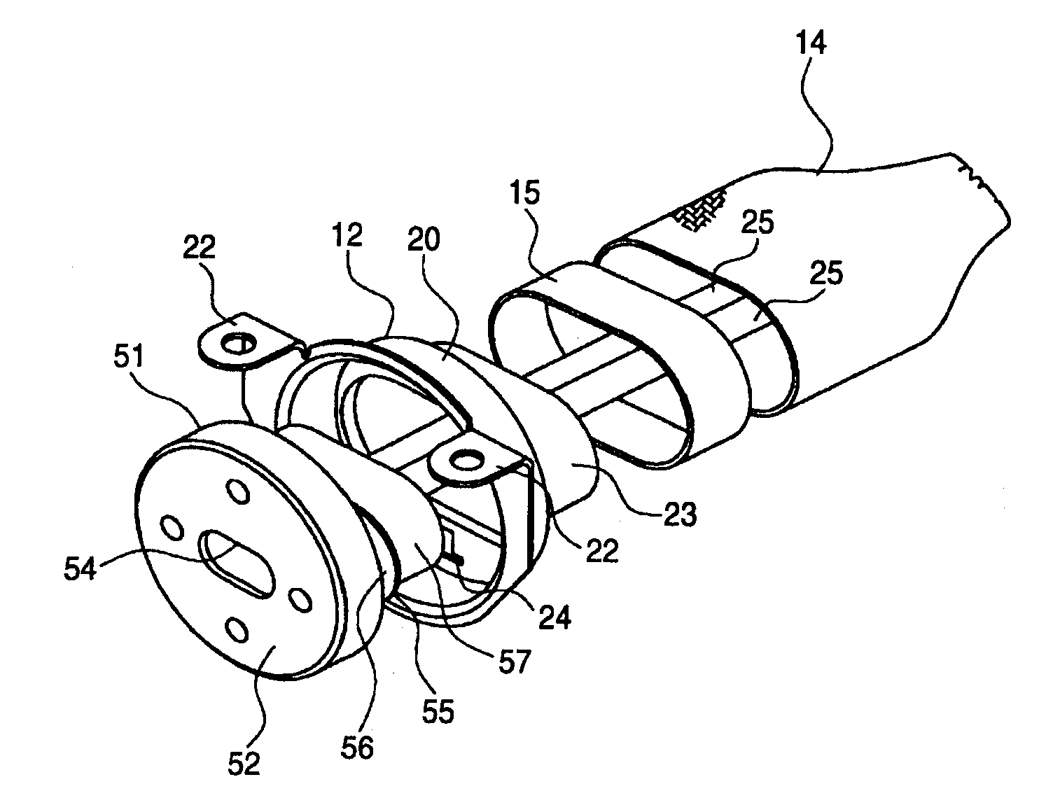
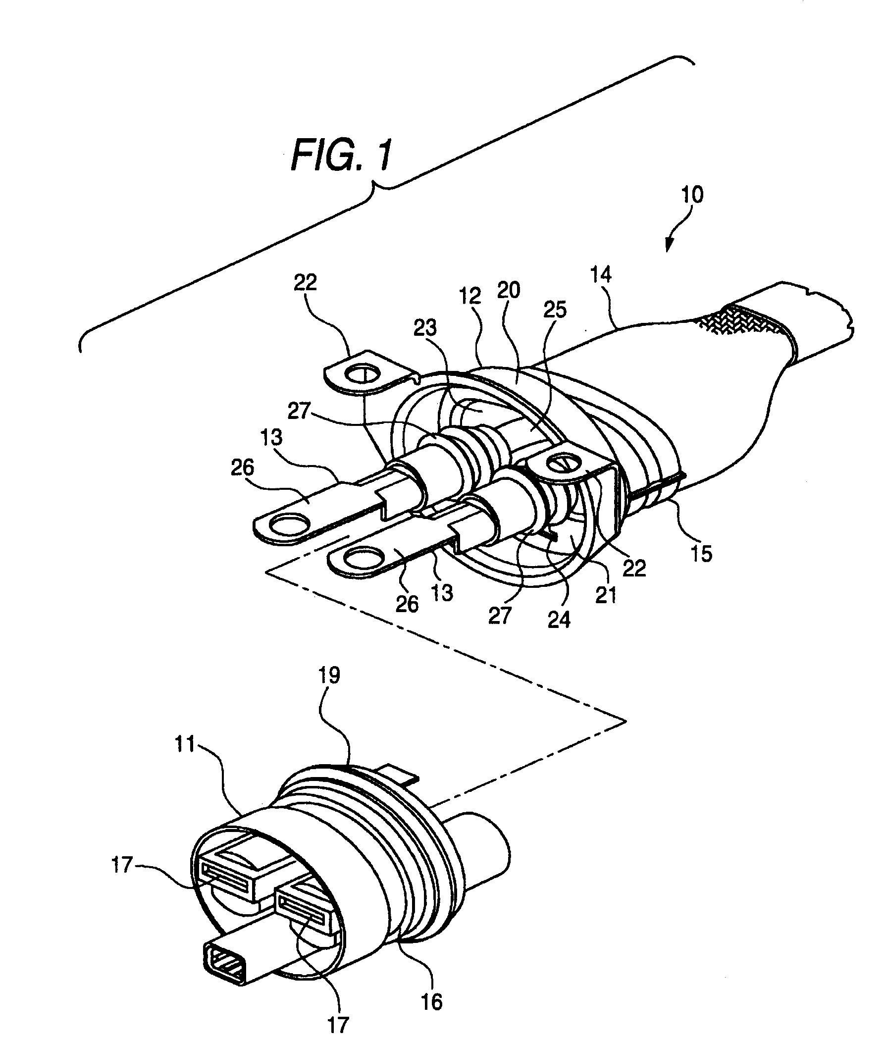
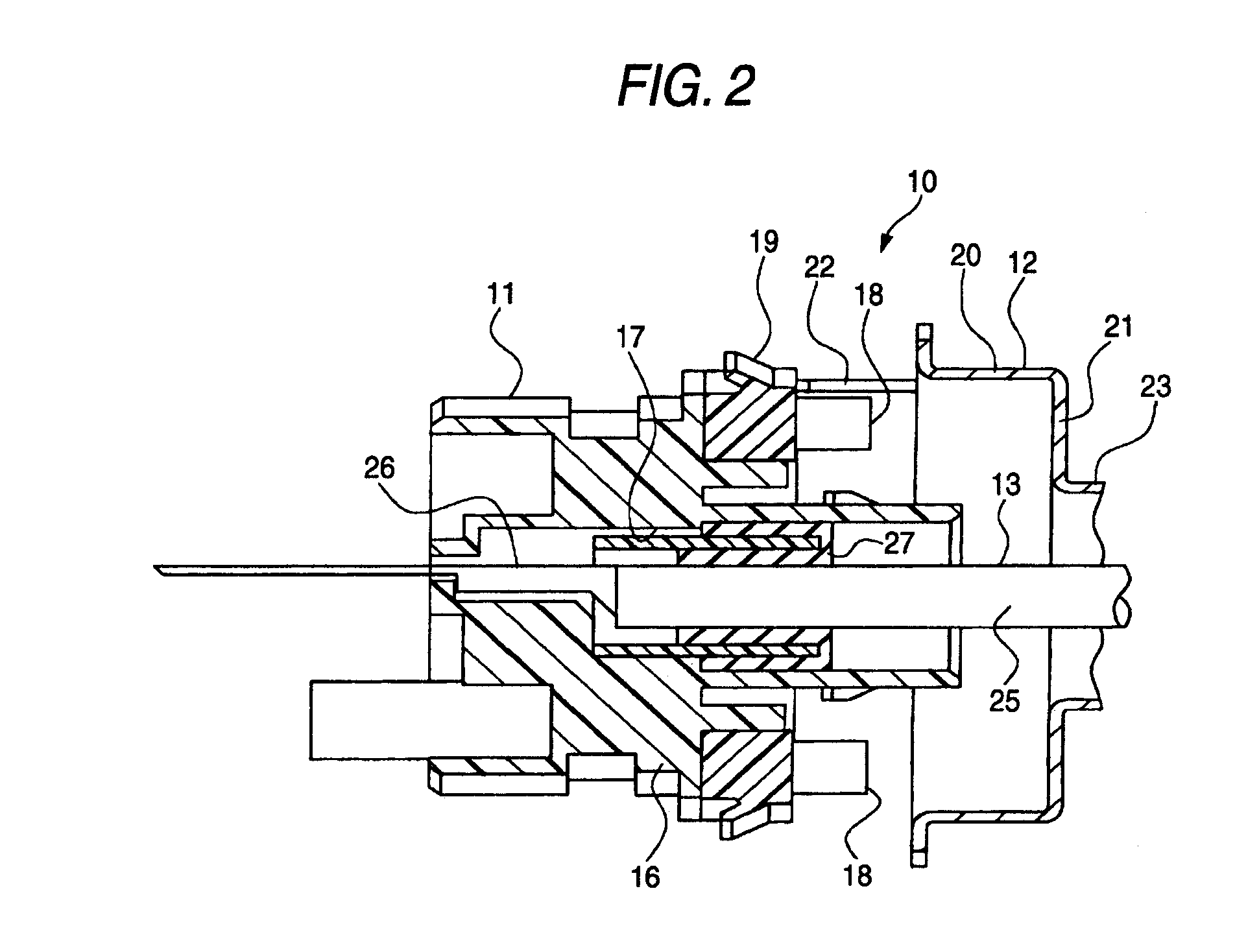
[0043]FIG. 1 through FIG. 6 show an embodiment of a shielded connector and a method of manufacturing a shielded connector according to the invention, FIG. 1 is a disassembled perspective view viewed from a side of a housing of a shielded connector according to an embodiment of the invention, FIG. 2 is a vertical sectional view around a terminal after integrating the shielded connector of FIG. 1, FIG. 3 is a disassembled perspective view before inserting a core for explaining a method of manufacturing the shielded connector according to the embodiment of the invention, FIG. 4 is a disassembled perspective view after inserting the core for explaining the method of manufacturing the shielded connector according to the embodiment of the invention, FIG. 5 is a vertical sectional view around a wire of FIG. 4 and FIG. 6 is a vertical sectional view around a wire aft...


PUM

PropertyMeasurementUnit
pressureaaaaaaaaaa
shapeaaaaaaaaaa
flexibleaaaaaaaaaa

Abstract

There is provided a method of manufacturing a shielded connector which includes: a terminal-attached wire; a housing containing the terminal of the terminal-attached wire; a shielded shell integrated to the housing; a knitted conductor mounted to the wire; and a shield ring interposing the knitted conductor between the shield ring and the shielded shell so that the knitted conductor is electrically connected to the shielded shell. The method includes: inserting, into the shielded shell, a single core having a stepped portion formed in a opposed drawing direction; bringing a contact portion formed at the shielded shell into contact with the core; covering the shield ring on the shielded shell via the knitted conductor; and calking the shield ring, the knitted conductor, and the shielded shell from outer side of the shield ring to form, on the shielded shell, a calk-deformed portion contained into the stepped portion of the core.

Description

[0001]This is a divisional of application Ser. No. 12 / 244,112 filed Oct. 2, 2008, The entire disclosure of the prior application, application Ser. No. 12 / 244,112 is considered part of the disclosure of the accompanying divisional application and is hereby incorporated by reference.BACKGROUND OF THE INVENTION[0002]1. Technical Field[0003]The present invention relates to a shielded connector integrating a shielded shell electrically connected with a knitted conductor by way of a shield ring to a housing containing a terminal of a terminal-attached wire and a method of manufacturing such a shielded connector.[0004]2. Background Art[0005]As an example of a shielded connector and a method of manufacturing a shielded connector, as shown by FIG. 7, there is known a shielded connector 70 containing split pieces 71 split into four to a flame 73 so that an outline of a vertical section thereof orthogonal to a direction of fitting a shielded shell 72 can expand and contract by way of spring me...

Claims


Application Information

Patent Timeline
Patent Type & Authority Applications(United States)
IPC IPC(8): H01R43/00
CPCH01R9/032H01R13/648Y10T29/49174Y10T29/49151Y10T29/49826H01R13/65912
Inventor AOKI, EIJIYAMANE, TOMOKAZUKANEKO, TAKEAKI
Owner YAZAKI CORP
Learn More