
Electronic fingerboard for stringed instrument

Inactive Publication Date: 2009-10-22
ELION CLIFFORD S
View PDF27 Cites 60 Cited by
  • Summary
  • Abstract
  • Description
  • Claims
  • Application Information

AI Technical Summary

Benefits of technology

[0023]The device of the present invention does not suffer from the inherent delay of pitch detection algorithms. The resistance value of the string sensor can be read instantaneously by the controlling microprocessor.
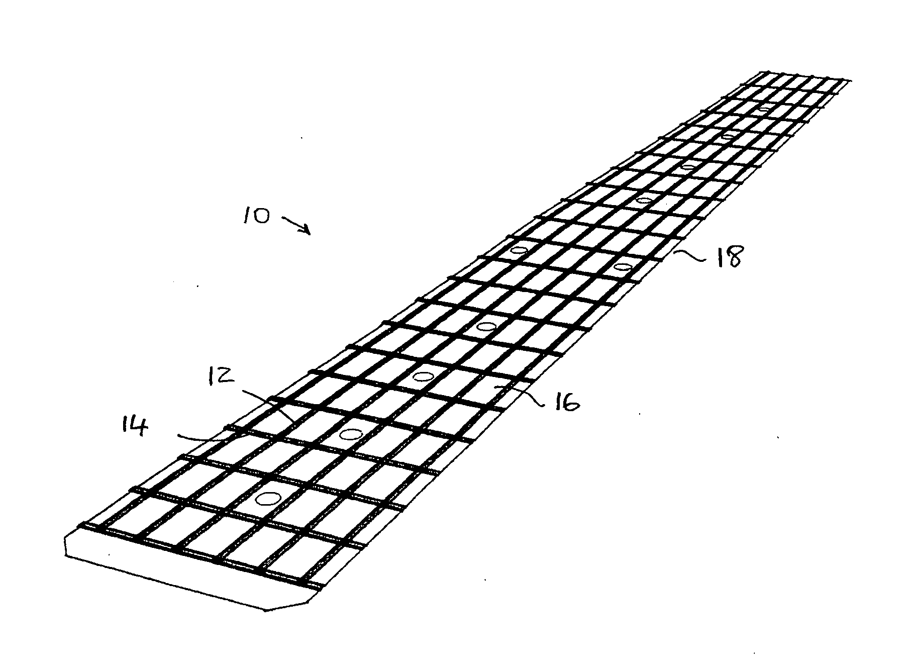
[0035]The fingerboard layout shown in FIG. 1 is used in the present embodiment of the invention. It is scaled to substantially match the fingerboard of a conventional stringed electric guitar. Many other configurations and scales are envisioned and fall within the scope of the invention. On a conventional guitar neck, the frets are spaced proportionally to the pitch of the note generated by the fingerboard position. Due to the fact that this system is electronic, the scale can be varied so that the frets, or fret markings, can be evenly spaced on the neck and also made smaller to provide a more compact system. The translation of finger position to actual pitch generated is determined by the software using a look-up table, mathematical equation or similar means that can also be varied to accommodate tunings of different stringed musical instruments.

Problems solved by technology

This method, however, is characterized by a physical delay between the time that the string is plucked and the time that the resulting note is generated.
The delay is due to the fact that a significant part of the electrical waveform must be analyzed before a result can be calculated and transmitted.
Typical systems need to acquire more than a single cycle before the pitch can be accurately determined, and this can result in delays that are not pleasing to musicians.
The problem with this type of system is that the switches in the neck are not very guitar-like for musicians familiar with conventional guitars as well as being expensive to implement.

Method used


Image

  • Electronic fingerboard for stringed instrument
  • Electronic fingerboard for stringed instrument
  • Electronic fingerboard for stringed instrument

Examples


Embodiment Construction

(A) Description of Conventional Fingerboard

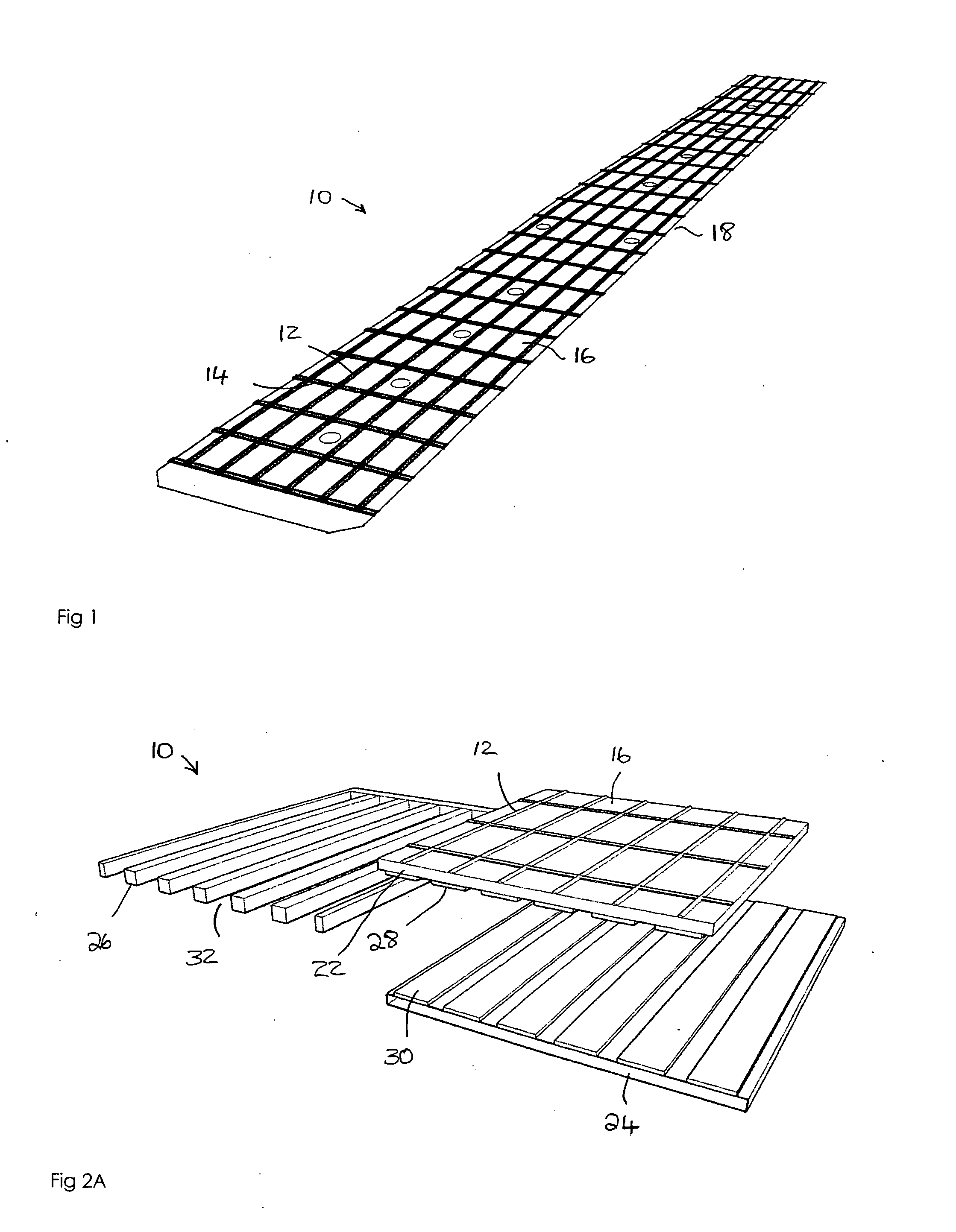
[0061]FIG. 1 shows a conventional fingerboard assembly 10 for use with the system of the invention. In this illustrated embodiment, the top layer of the fingerboard assembly 10 has strings 12 and frets 14 that are embossed on the surface 16 of the fingerboard assembly 10, and these raised markers for the strings 12 and frets 14 provide tactile feedback to the user. The strings 12 and / or the frets 14 could be omitted from the design. The process of marking chosen for this embodiment is to emboss these features onto the top overlay or surface 16 of the fingerboard assembly 10. Other methods include silk-screening the features with durable epoxy based ink. In another embodiment, there is use of a k round plastic rib that is adhered along its flat end or surface along the length of the neck 18 to simulate the tactile feeling of a string 12.

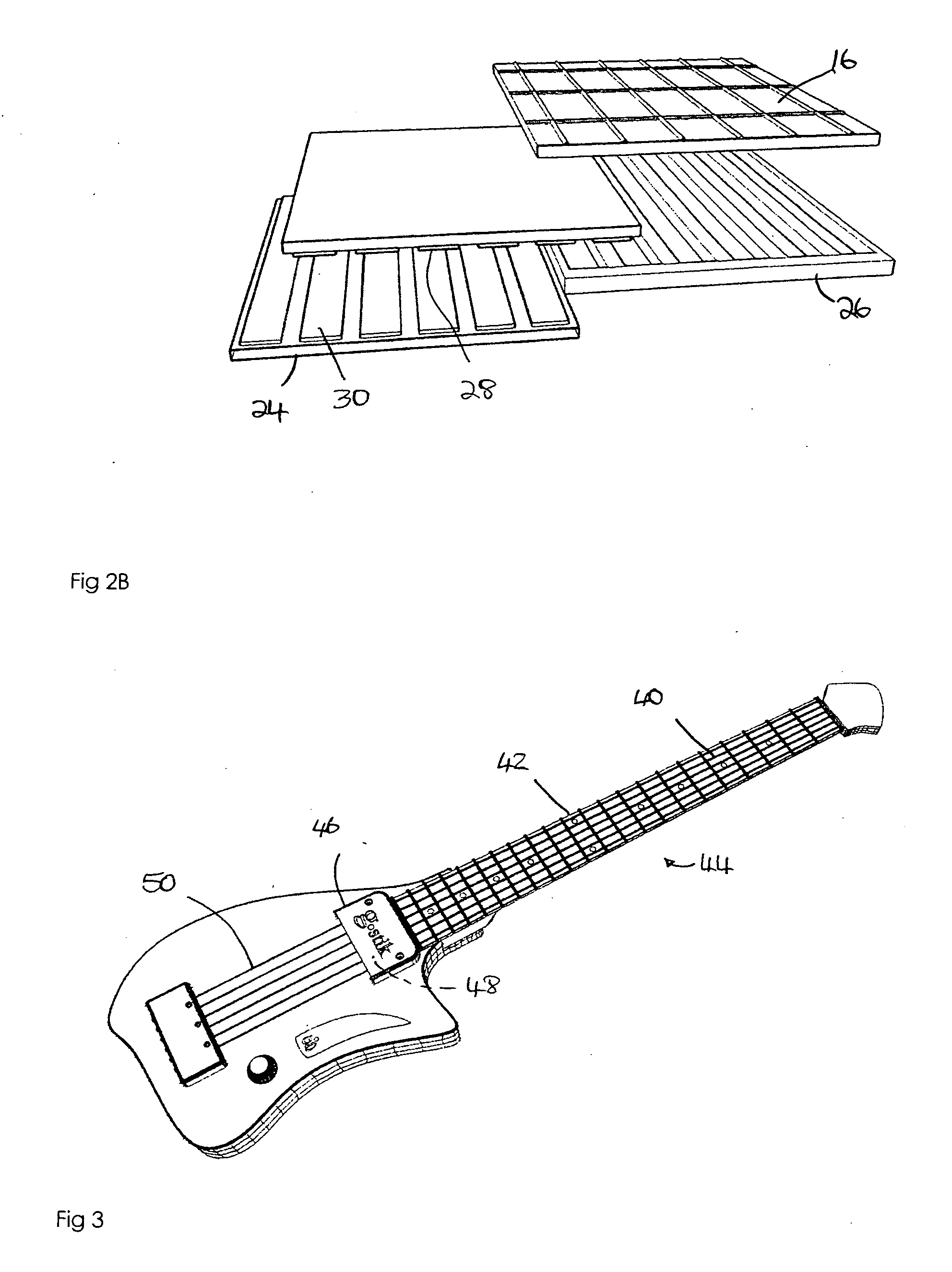
[0062]FIG. 2 of the drawings shows an exploded cross section of the fingerboard assembly 10 in accordance ...


PUM


Abstract

An electronic musical instrument for producing musical notes comprises an onset signal sensor for sensing the initiation of a note played on the musical instrument. An electronic fingerboard determines the pitch of the note sensed by the sensor. The electronic fingerboard comprises a first layer of film, a second layer of film and a spacer member between the first and second layers of film. The first and second layers are movable relative to each other between a first inactive position in which the first and second layers are separate from each other along their respective lengths and a second active position in which the first and second layers are in contact with each other at a user selected point along their respective lengths. The pitch is determined by the resistance between the first and second layers at the user selected point.

Description

CROSS REFERENCE TO RELATED APPLICATIONS[0001]This application is a continuation in part application of U.S. patent application Ser. No. 12 / 284,953 filed Sep. 26, 2008, which claims the benefit of U.S. Provisional Patent Applications Nos. 60 / 976,413 filed Sep. 29, 2007 and 61 / 011,259 filed Jan. 16, 2008, all of which are incorporated by reference in their entirety. Further, this application claims the benefit U.S. Provisional Patent Applications Nos. 61 / 145,735 filed Jan. 19, 2009 and 61 / 149,696 filed Feb. 3, 2009, which are incorporated by reference in their entirety.FIELD AND BACKGROUND OF THE INVENTION[0002]The present invention relates to an interface for controlling musical instrument synthesizers. In one aspect, the present invention allows musicians familiar with stringed instruments to use their musical skill to control electronic music synthesizers.[0003]According to one aspect of the invention, there is provided a synthesizer controller based on a guitar interface, but the ...

Claims


Application Information

Patent Timeline
IPC IPC(8): G10H1/34G10D3/06
CPCG10H1/0066G10H2220/301G10H2220/096G10H1/342
Inventor ELION, CLIFFORD S.
Owner ELION CLIFFORD S
Learn More