Apparatus for Compensating and/or Transmitting Forces or Torques and Rotational Movements Between Two Components

a technology of torque and transmission shaft, applied in the direction of resilient suspension, interconnection system, vehicle spring, etc., can solve the problems of large frictional force acting through the thread, inability to integrate, and inability to provide output shafts, etc., and achieve the effect of small installation space and simple design

Inactive Publication Date: 2009-10-22
ASTURIA AUTOMOTIVE SYST
View PDF6 Cites 7 Cited by
  • Summary
  • Abstract
  • Description
  • Claims
  • Application Information

AI Technical Summary

Benefits of technology

[0013]A further object of the invention is to provide an apparatus for the compensation and / or transmission of forces / torques and rotational movements between two components which has a simple construction and can be manufactured without undue effort or expense.
[0052]Thus, an apparatus for the compensation and / or transmission of forces / torques and rotational movements between two components is provided by the arrangement according to the invention, which is particularly useful for the compensation of vehicle movements and is usable in a variety of ways and has a simple design and requires little installation space

Problems solved by technology

The large frictional forces which act through the thread are a disadvantage.
Furthermore, it is a disadvantage that the output shaft comprises two partial sections, to which a torque is applied in the same rotational direction.
It is not possible with this arrangement to transmit different and even opposing torques onto the two shaft sections.
This arrangement is therefore not suitable for compensating forces and torques between two components.
The use of the two limiters requires a large installation space and is relatively complex.
It is a disadvantage that these actuators have a complex gearing.
The relatively large installation space and the still somewhat complex construction are disadvantageous.
Furthermore, this arrangement only has one shaft output, which limits its potential field of use.

Method used


Image

  • Apparatus for Compensating and/or Transmitting Forces or Torques and Rotational Movements Between Two Components
  • Apparatus for Compensating and/or Transmitting Forces or Torques and Rotational Movements Between Two Components
  • Apparatus for Compensating and/or Transmitting Forces or Torques and Rotational Movements Between Two Components

Examples


Embodiment Construction

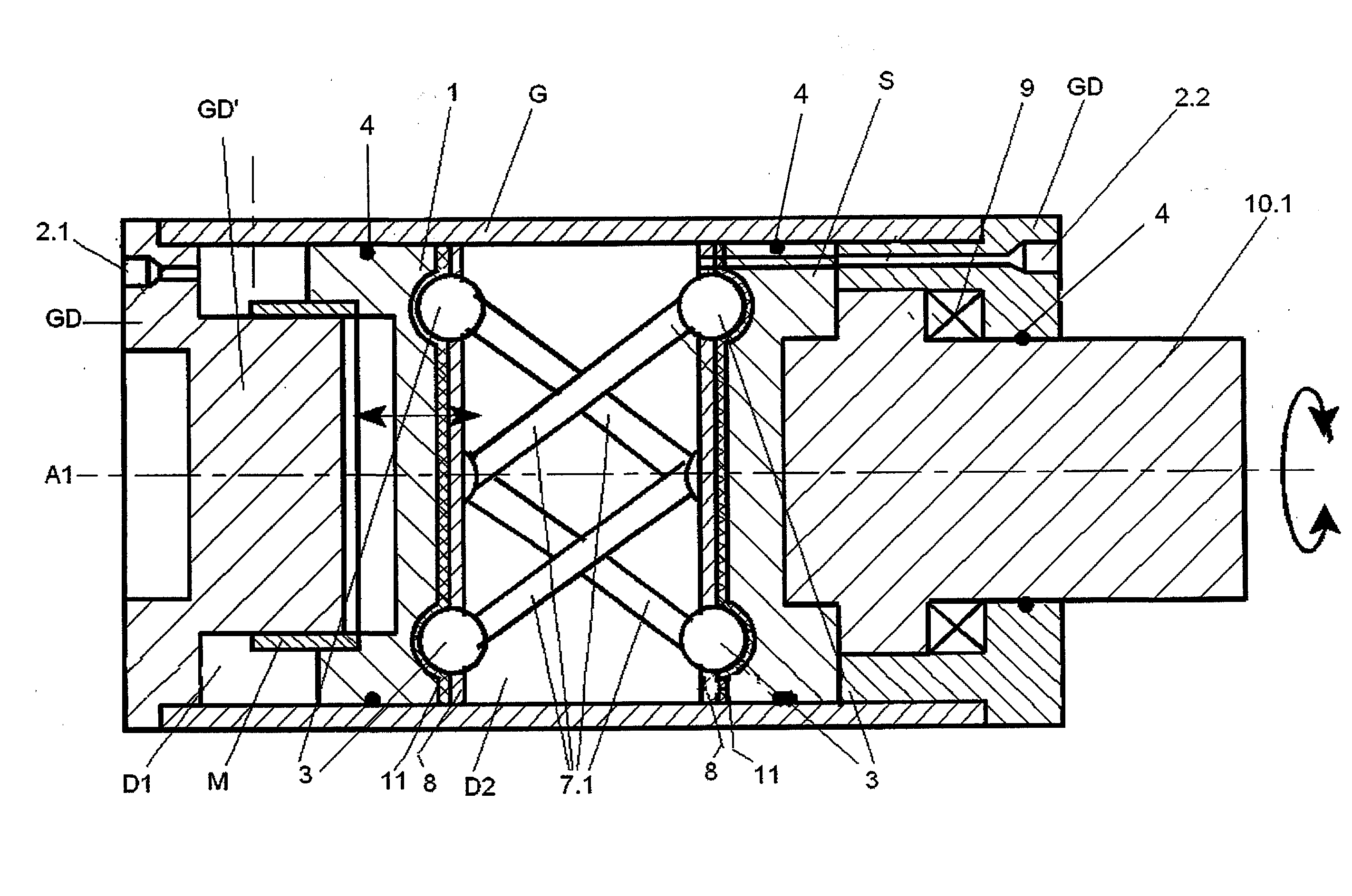
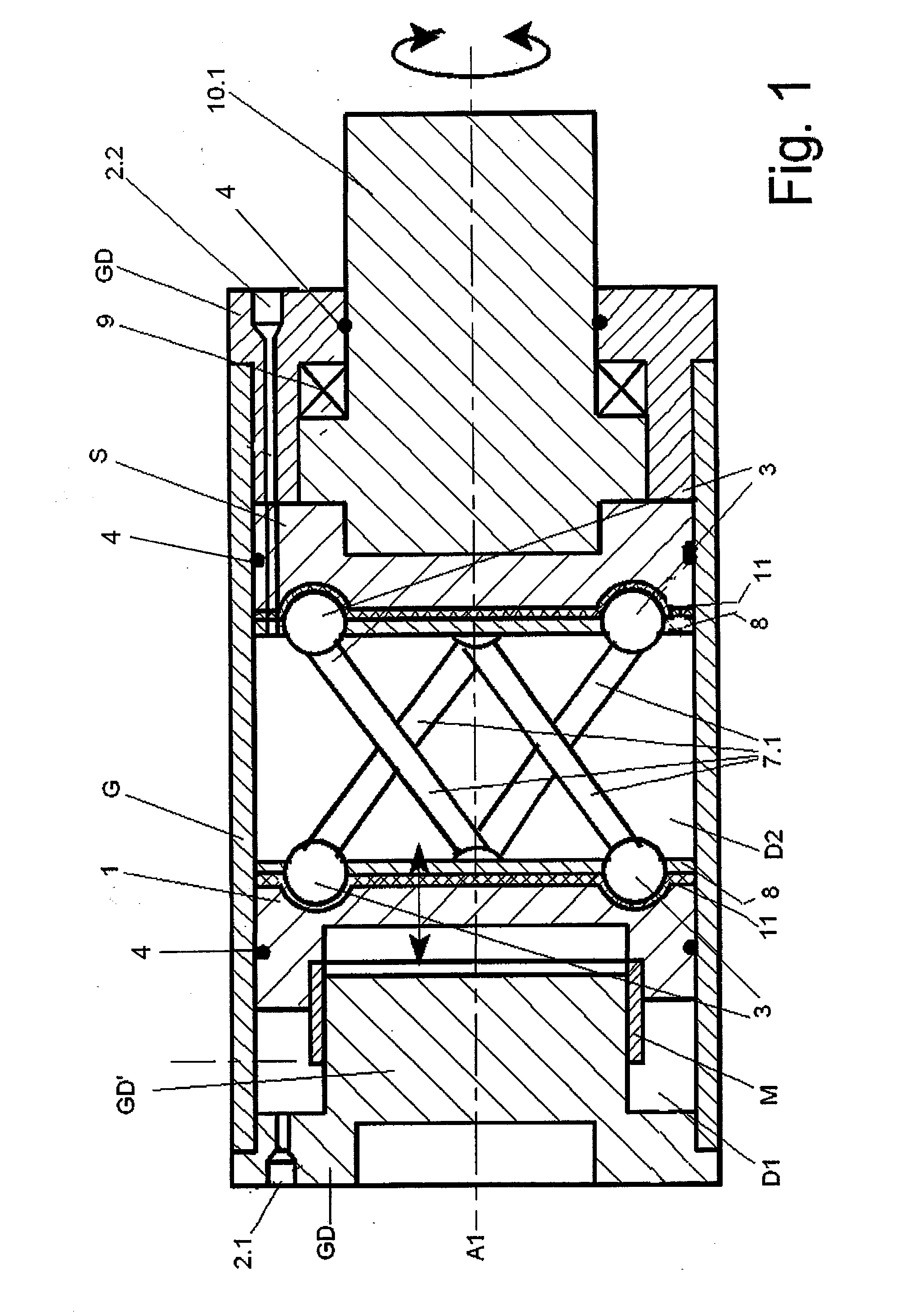
[0068]FIG. 1 shows the schematic illustration of a joint module comprising a rotatable shaft 10.1 and axial pressure medium feeds 2.1, 2.2 in the starting position. A piston 1 is situated in a housing G and which is mounted via a spline-toothed sliding sleeve M so that the piston is rotationally fixed and axially displaceable. The sliding sleeve M is seated on a projection GD′, which extends in the direction toward the piston, of the housing cover GD, which closes the housing G on the left side of the figure. A first pressure chamber D1, to which the first pressure medium feed line 2.1 leads, is formed between piston 1 and housing cover GD.

[0069]The balls 3 at one end of four ball rods (first coupling elements 7.1) are pivotably mounted in ball sockets (not shown in greater detail) on the side of the piston 1 facing away from the housing cover GD via a fastening ring 8 and a piston-side socket ring 11. The balls 3 at the opposite ends of the ball rods (first coupling elements 7.1) a...


PUM


Abstract

An apparatus for compensating and / or transmitting forces / torques and rotational movements between two components, particularly for compensating for vehicle movements, in which at least one joint module is situated between the two components, which joint module converts a translational and / or rotational movement of a piston, to which a pressure medium is applied, into a rotational movement of at least one first rotatable shaft or of a first and a second rotatable shaft.

Description

CROSS REFERENCE TO RELATED APPLICATIONS[0001]This application is a continuation of international patent application no. PCT / DE2006 / 001894, filed Oct. 27, 2006, designating the United States of America, and published in German on May 2, 2008 as WO 2008 / 049382, the entire disclosure of which is incorporated herein by reference. Priority is claimed based on Federal Republic of Germany patent application no. DE 20 2006 016 354.9, filed Oct. 23, 2006.BACKGROUND OF THE INVENTION[0002]The invention relates to an apparatus for the compensation and / or transmission of forces / torques and rotational movements between two components, and is used in particular for the compensation of vehicle movements, e.g., in an active chassis of a motor vehicle in order to stabilize the suspension.[0003]A linear pivot drive, in particular for the flap control of aerodynamic structures, is known from US 2005 / 525516 (=WO 03 / 072955). It comprises a housing, in which a piston is situated so it is axially displacea...

Claims


Application Information

Patent Timeline
Patent Type & Authority Applications(United States)
IPC IPC(8): F15B13/00
CPCB60G21/0555F15B15/06B60G2202/413
Inventor LEZOCK, DANIELFREUND, WOLFGANGSCHULZE, JUERGEN
Owner ASTURIA AUTOMOTIVE SYST
Why Eureka
Try Eureka