Method and welding apparatus for the determination of the strength of the welding current to be used in the welding of container bodies

a technology for welding containers and welding currents, which is applied in the direction of resistive welding apparatus, welding electric supply, domestic vessels, etc., can solve the problems of body unfit for further use, too easily broken seams, and welding with a high temperature, and achieve good tearing open capability of seams and high current strength

Active Publication Date: 2009-10-22
SOUDRONIC
View PDF13 Cites 3 Cited by
  • Summary
  • Abstract
  • Description
  • Claims
  • Application Information

AI Technical Summary

Benefits of technology

[0007]In a preferred embodiment the current strength variation along the seam of the test body is not steady but instead has at least one inflexion point with different slopes on both sides of the inflexion point. In regard to the test body this allows that in the region of the higher welding current strength a lower slope of the current strength change is used and that in the region of the smaller welding current strength a steeper slope of the welding current strength change is used. This provides a better recognition of the “spat...

Problems solved by technology

If the welding current strength in the case of the test welding was set too low, or if the welding temperature was too low, the seam can too easily become broken open, since an insufficient material melting was achieved, which is also designated as “adhesion”.
On the other hand if the welding curr...

Method used


Image

  • Method and welding apparatus for the determination of the strength of the welding current to be used in the welding of container bodies
  • Method and welding apparatus for the determination of the strength of the welding current to be used in the welding of container bodies
  • Method and welding apparatus for the determination of the strength of the welding current to be used in the welding of container bodies

Examples


Embodiment Construction

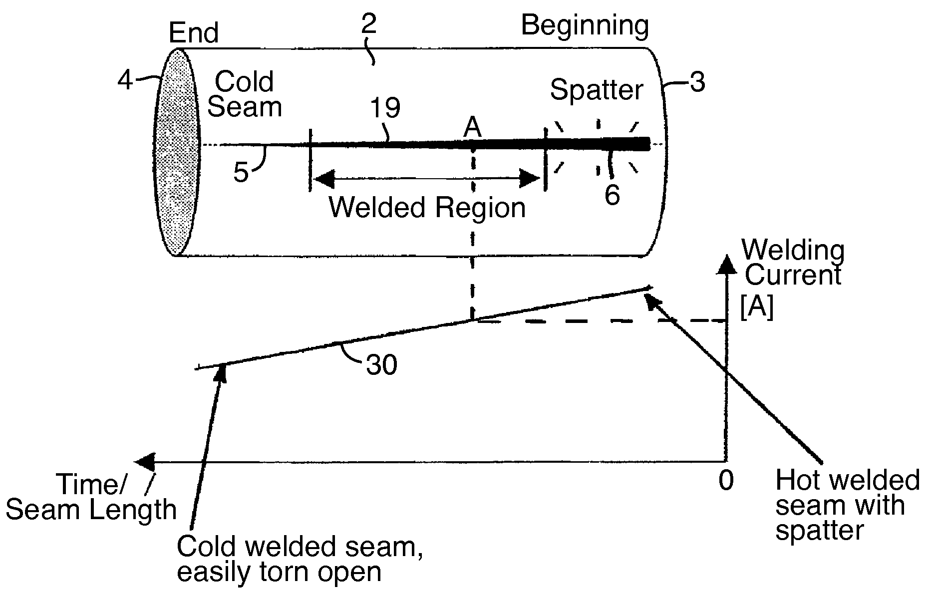
[0014]FIG. 1 shows schematically a test container body 2, which serves for the determination of the appropriate welding current strength value to be used for the serial production of bodies made from the same sheet material as the test body, above a diagram which illustrates the welding current strength along the length of the seam of the test body 2, or correspondingly in respect to the time needed for the welding. The test body 2 is welded on a resistance seam welding machine or roller seam welding machine, which is explained in more detail in connection with FIG. 3. According to the invention now the strength of the welding current during the test welding of the body 2 along the overlapped welding seam is varied so as to fall or rise. In the illustrated example the welding current strength 30 falls during the time of the welding, or along the length of the seam, and accordingly diminishes from a starting value to an ending value. The welding current in this case, as in known ways...


PUM

PropertyMeasurementUnit
Lengthaaaaaaaaaa
Currentaaaaaaaaaa
Strengthaaaaaaaaaa

Abstract

For the determination of the welding current to be used for the resistance welding of the overlap seam of container bodies, welding with a test body is carried out with a changing strength of welding current which in the test body produces a varying welding of the seam. The current strength varies from welding of this seam with a too high temperature to welding with a too low temperature. Along with this the welding current strength used in the welding is determined so that it is further determined at which point of the seam the welding has been accomplished and with what strength of welding current. By means of a mechanical and/or optical investigation of the welded seam it can then be easily determined where the seam has been correctly welded for the series production of container bodies from the same sheet material as the test bodies. When such a point or such a region of the seam is known the welding current used in the test welding can be taken as the welding current for serial production.

Description

CROSS REFERENCE TO RELATED APPLICATION[0001]This application claims the priority of Swiss patent application No. 0605 / 08, filed on Apr. 17, 2008 the disclosure of which is incorporated herein by reference in its entirety.BACKGROUND OF THE INVENTION[0002]The invention concerns a method for determining the strength of the welding current to be used for the resistance seam welding of container bodies sequentially following one another. The invention also concerns a welding apparatus for the resistance seam welding of container bodies, with welding rolls, a welding current generator and a welding current control. The invention further concerns a method for the resistance seam welding of container bodies with nonuniform overlapping as well as a welding apparatus for the resistance seam welding of container bodies with nonuniform overlapping.STATE OF THE ART[0003]For setting the strength of the welding current for the resistance seam welding of container bodies it is customary to carry ou...

Claims


Application Information

Patent Timeline
IPC IPC(8): B23K11/24B23K11/08
CPCB23K11/066B23K2201/125B23K11/257B23K11/0876B23K9/092B23K11/0026B23K11/062B23K11/24B23K11/248B23K31/12B23K2101/125
Inventor ZIEGLER, PATRICK
Owner SOUDRONIC
Why Eureka
Try Eureka