

Rotating electrical machine
- Summary
- Abstract
- Description
- Claims
- Application Information
AI Technical Summary
Benefits of technology
Problems solved by technology
Method used
Image

Examples
first embodiment
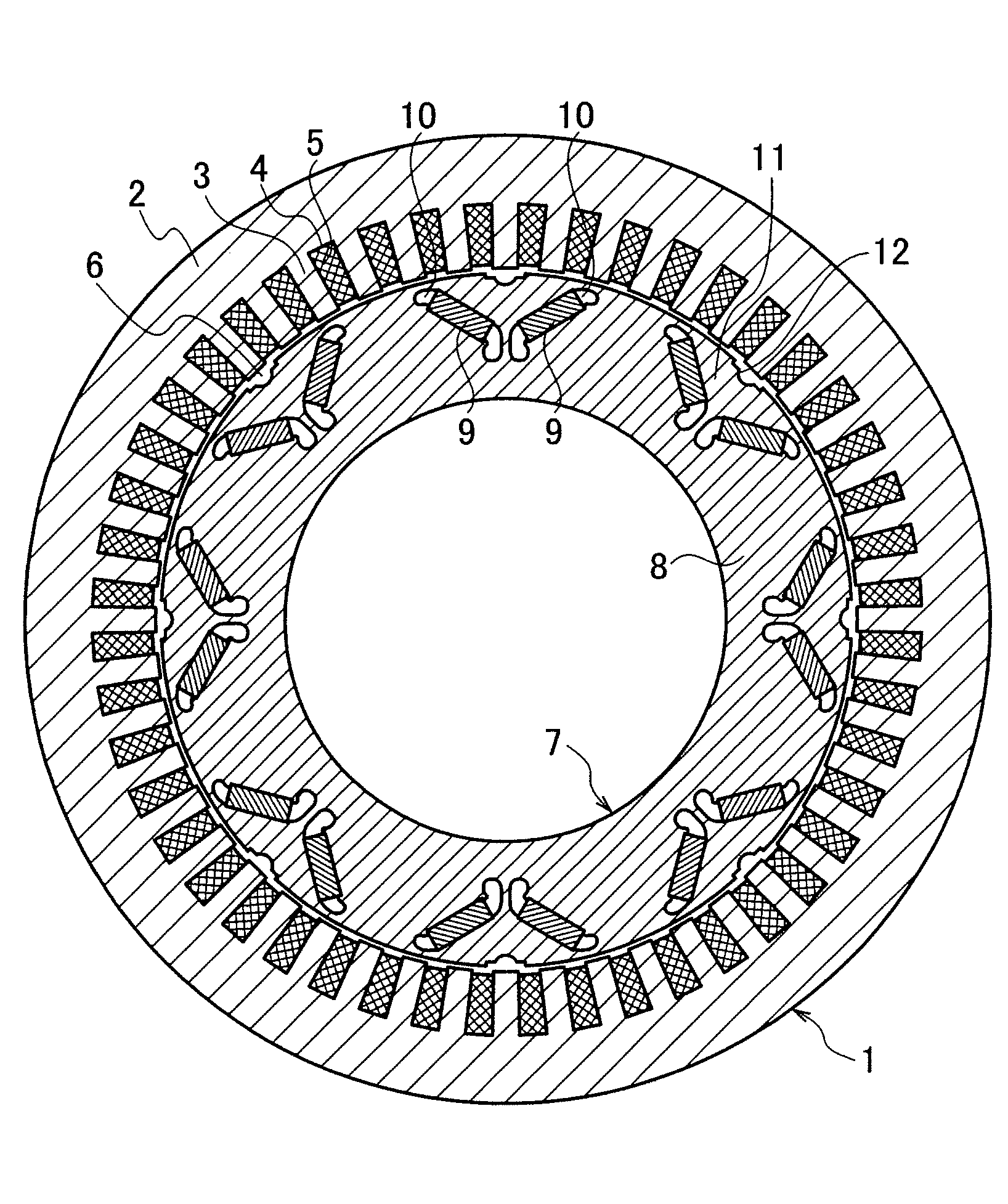
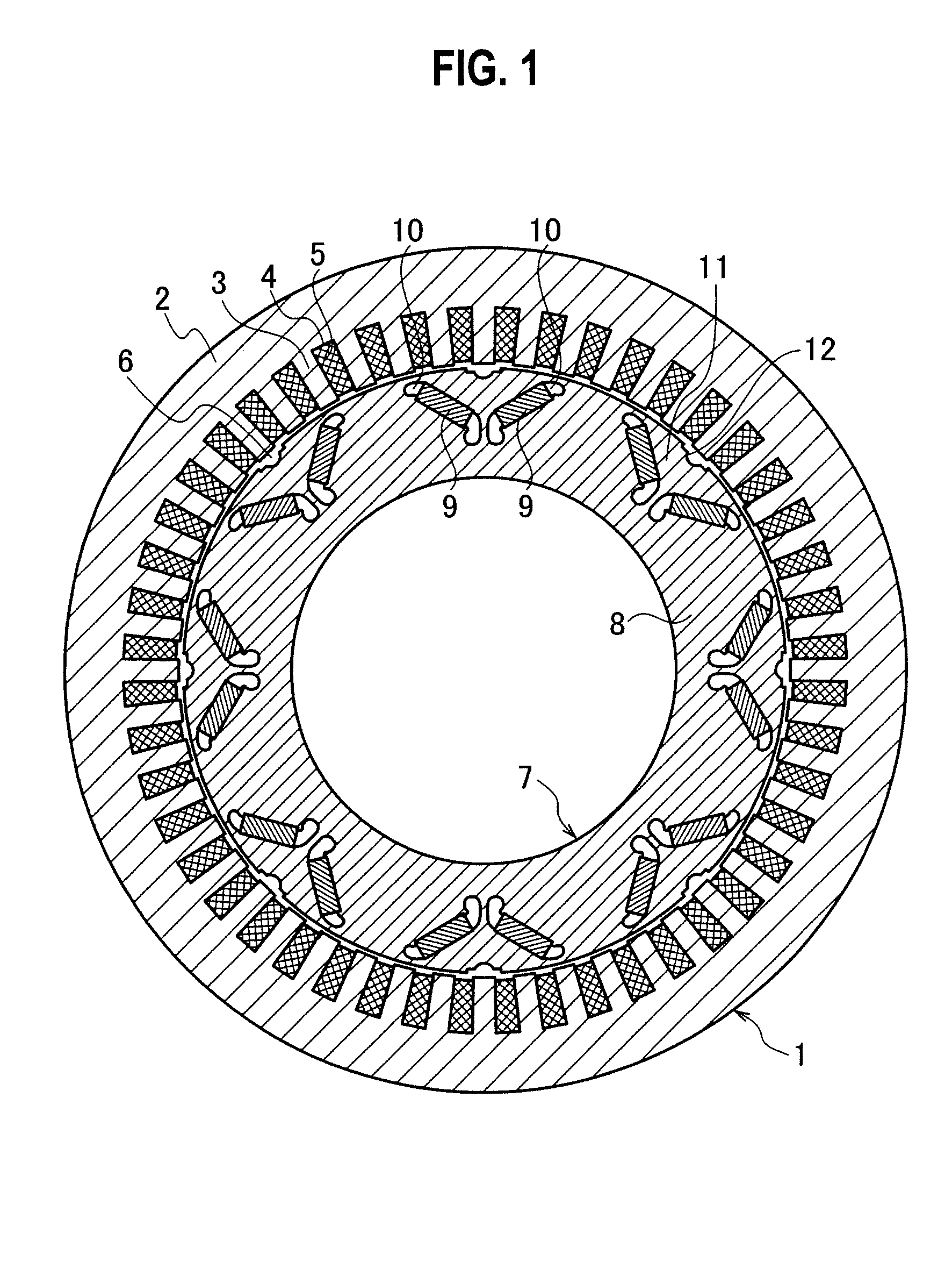
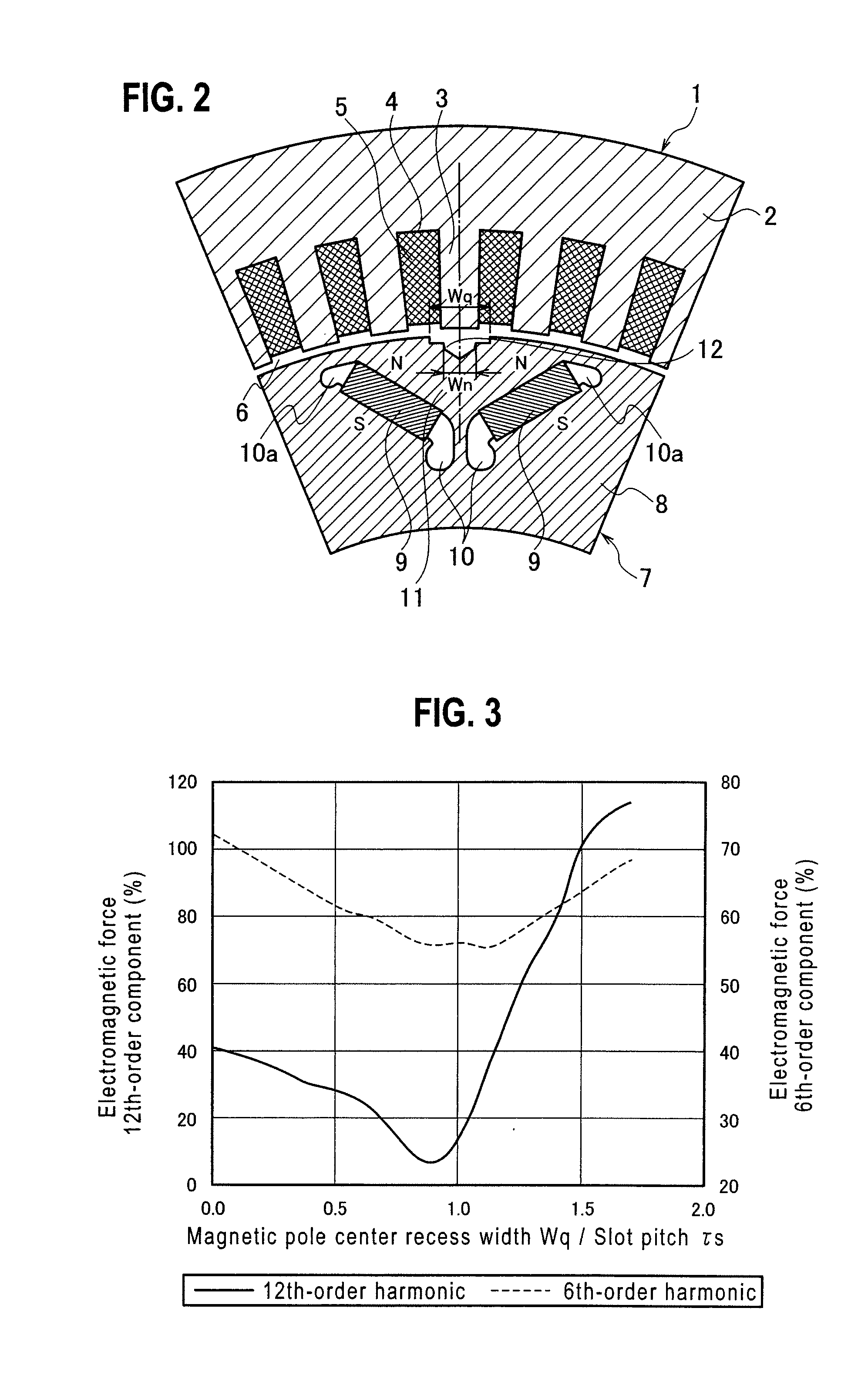
[0046]FIG. 1 is a sectional view showing the first embodiment of the present invention and FIG. 2 is an enlarged sectional view showing a pole area of the first embodiment. As shown in FIG. 1, this rotating electrical machine has eight poles and 48 slots. A stator 1 has a stator iron core 2. The stator iron core 2 is formed by laminating a plurality of annular magnetic steel sheets each having iron core teeth 3 and the slots 4 alternated in a circumferential direction. Each slot 4 accommodates a coil 5.
[0047]Inside the stator 1, a rotor 7 is arranged with an air gap 6 interposed between them. The rotor 7 has a rotor iron core 8. The rotor iron core 8 is formed by laminating a plurality of annular magnetic steel sheets.
[0048]In the rotor iron core 8, a plurality of NdFeB-based permanent magnets 9 are embedded. Namely, the permanent magnets 9 are embedded in pairs of cavities 10 that are arranged at magnetic pole forming positions that are set at regular angular intervals along an out...
second embodiment
[0055]FIG. 4 is an enlarged sectional view showing a pole area of a rotating electrical machine according to the second embodiment of the present invention. In each of the embodiments that follow, parts corresponding to those of already explained embodiments are represented with the same reference marks to omit repetitive explanations.
[0056]This embodiment forms an axially extending recess 13 on a face of a rotor iron core 8 that fronts an air gap 6, so that, in a state that an axis passing through a center of circumferential width of an iron core section 11 and the center of a rotor 7 agrees with an axis passing through a center of circumferential width of an iron core tooth 3 and the center of the rotor 7, an axis passing through a center of circumferential width of the recess 13 formed on the rotor iron core 8 and the center of the rotor 7 and an axis passing through a center of circumferential width of a slot 4 adjacent to the recess 13 and the center of the rotor 7 form an angl...
third embodiment
[0064]FIG. 6 is an enlarged sectional view showing a pole area of the third embodiment of the present invention. This embodiment forms an axially extending recess 14 on a face of a rotor iron core 8 that fronts an air gap 6, so that, in a state that an axis passing through a center of circumferential width of an iron core section 11 of a rotor 7 and the center of the rotor 7 agrees with an axis passing through a center of circumferential width of an iron core tooth 3 of a stator 1 and the center of the rotor 7, an axis passing through a center of circumferential width of the recess 14 formed on the rotor iron core 8 and the center of the rotor 7 and an axis passing through a center of circumferential width of a slot 4 adjacent to the recess 14 and the center of the rotor 7 form an angle α3=τs×0.249.
[0065]Here, the angle between the recess 14 and the slot 4 has a negative value when the central axis of the recess 14 with respect to the central axis of the slot 4 is positioned on the ...
PUM
 Abstract
Description
Claims
Application Information