Battery charge compensation

Active Publication Date: 2009-10-22
TEXAS INSTR INC
View PDF17 Cites 47 Cited by
  • Summary
  • Abstract
  • Description
  • Claims
  • Application Information

AI Technical Summary

Benefits of technology

[0010]An aspect of the invention provides a method and apparatus for measuring, directly or indirectly, the voltage being applied to the cells in a rechargeable battery pack, and modifying the

Problems solved by technology

The constant current during the first phase replenishes much of the battery energy, but if such constant current is continued after the battery voltage rises above its OCV, it will overcharge and destroy the battery, possibly with catastrophic results such as fire or explosion.
Too high a current during the CC phase, or continuing the CC phase after the cells reach their OCV value, causes overheating and damage to cells.
A voltage above OCV during the CV phase typically causes irreversible, damaging chemical changes in the cell.
For example, during the CV phase and due to combin

Method used


Image

  • Battery charge compensation
  • Battery charge compensation
  • Battery charge compensation

Examples


Embodiment Construction

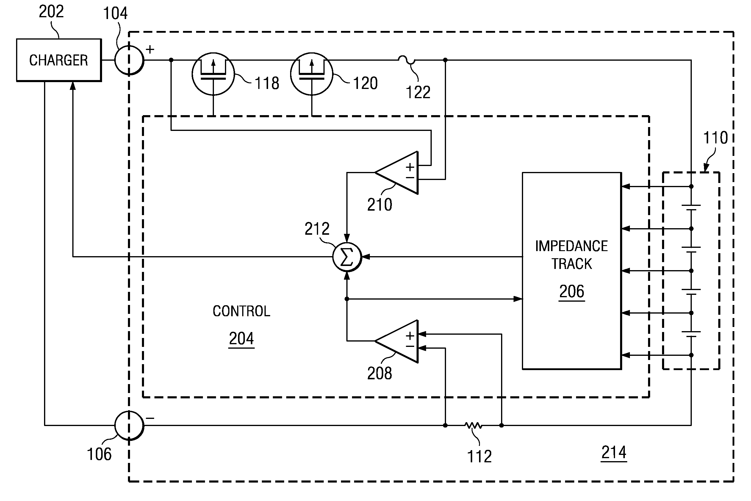
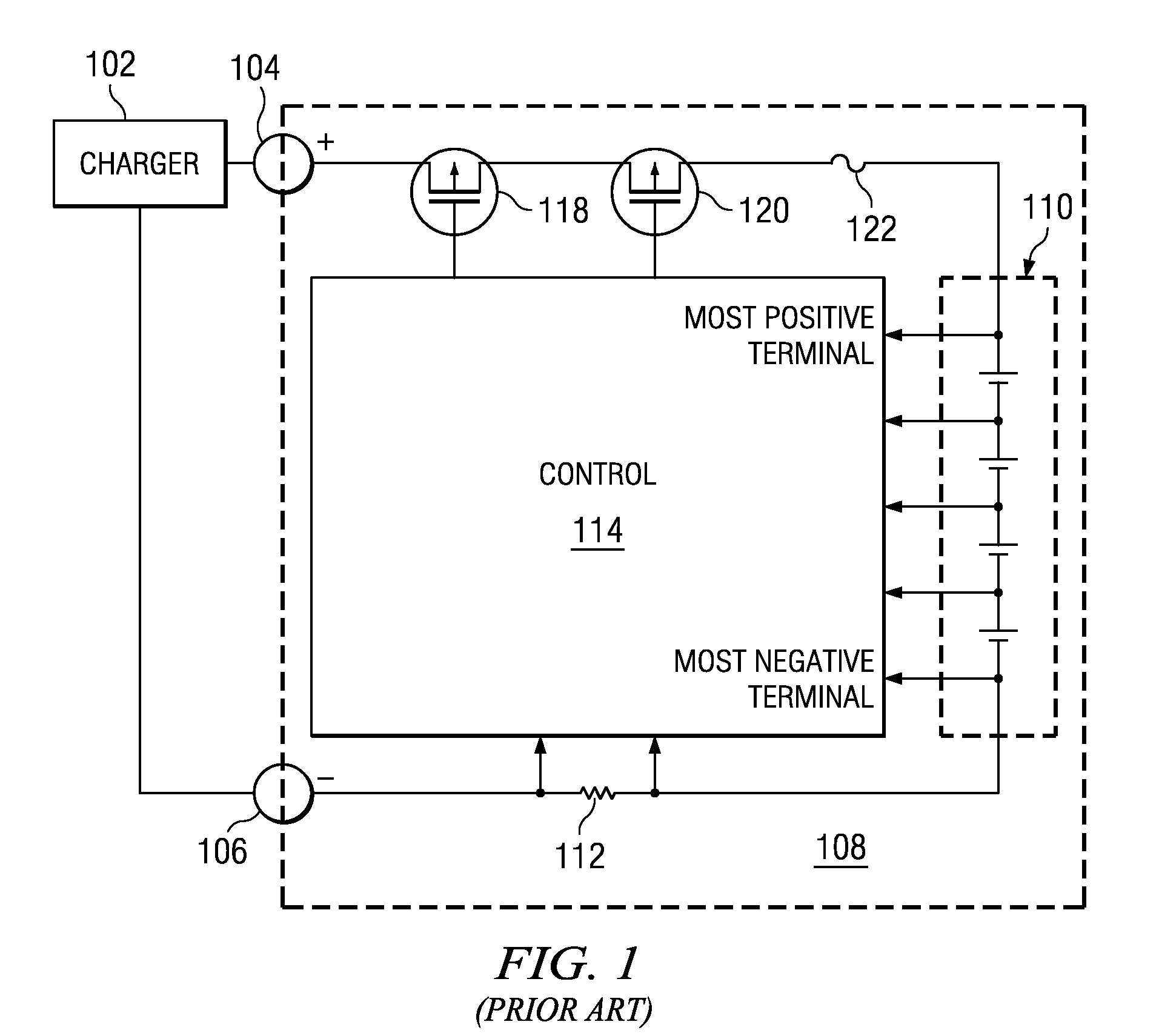
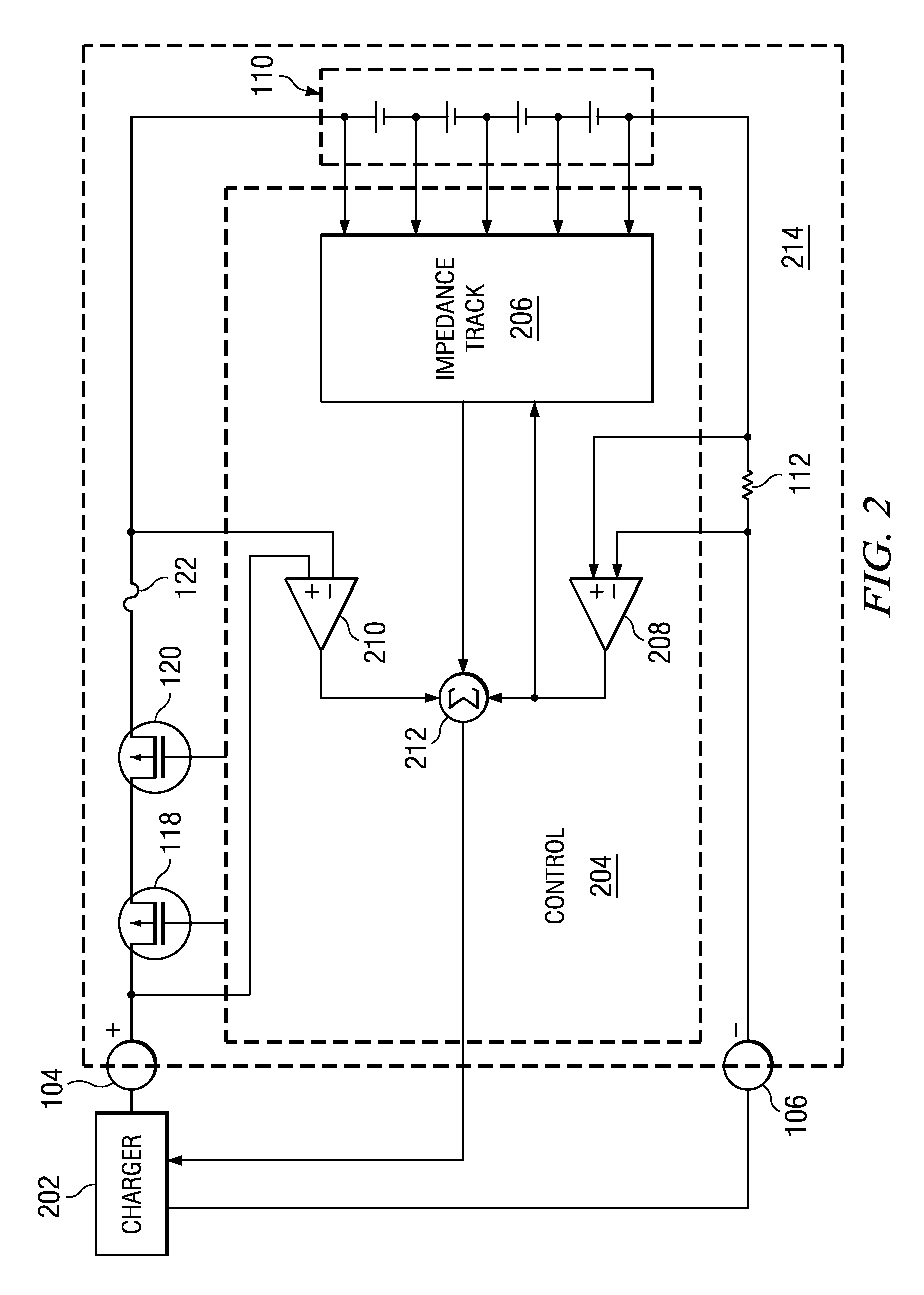
[0029]In FIG. 1, a charger 102 has a positive output coupled to the positive terminal 104 of battery pack 108, and a negative output coupled to the negative terminal 106 of the battery pack. Switching and protection elements comprise charge FET 118, discharge FET 120, and fuse 122. FET 118 has a first terminal coupled to the positive terminal 104, a second terminal coupled to the first terminal of FET 120, and a third control terminal. FET 120 has a first terminal coupled to the second terminal of FET 118, second terminal coupled to a first terminal of fuse 122, and a third control terminal. The second terminal of fuse 122 is coupled to a first terminal of cells 110 which is the most positive voltage of cells 110. Another terminal of cells 110 which is the most negative voltage of cells 110 is coupled to a first terminal of sense resistor 112. A second terminal of sense resistor 112 is coupled to the negative terminal 106. A control circuit 114 has a first terminal coupled to the th...


PUM


Abstract

A battery charger and method for a rechargeable battery pack which includes various elements in series with the cells to be charged, including but not limited to current control FETs, a fuse, current sense resistor, and internal series impedance of the series connected cells to be charged. The charging current Ichg flowing through these series elements reduces the voltage applied to the cells, thus lengthening charging time. A compensation voltage Vcomp, which when added to the nominal charging voltage for the series connected cells overcomes these voltage drops, facilitates more efficient charging while avoiding over-voltage damage to the cells. Three voltages representing substantially all of the voltage drops reducing the charging voltage on the cells, are summed, and the result is a compensation voltage which is utilized to change the nominal charge voltage for the battery to overcome these voltage drops.

Description

BACKGROUND OF THE INVENTION[0001]1. Field of the Invention[0002]This invention relates generally to battery charging, and more specifically to optimizing the charging current and charging voltage applied to a battery pack by compensating for voltage drops within the battery pack, so as to reduce charge time and increase charging efficiency, while keeping battery cell voltages and currents at safe levels to minimize damage to the cells being charged.[0003]2. Description of the Related Art[0004]Rechargeable battery packs (also referred to herein as batteries) are widely used to power portable devices such as laptop computers, cell phones, cameras, and power tools. A battery pack is a series-connected set of one or more cells (hereinafter referred to as cells). It is desirable for such battery packs to have high capacity (generally measured in ampere-hours), to be lightweight, small, and able to be rapidly recharged.[0005]Various cell chemistries have been developed for rechargeable ba...

Claims


Application Information

Patent Timeline
IPC IPC(8): H02J7/04
CPCH02J7/0072H02J7/007182
Inventor HSU, TSINGBARSUKOV, YEVGENMARTINEZ, ROBERTMIGNANO, PETER
Owner TEXAS INSTR INC
Why Eureka
Try Eureka