Image processing apparatus and image processing method

a technology of image processing and image processing, applied in the field of image processing apparatus and image processing method, can solve the problems of not being able to use artificial markers, not knowing registration problems, and unable to register, and achieve the effect of improving registration accuracy

Active Publication Date: 2009-10-22
CANON KK
View PDF11 Cites 66 Cited by
  • Summary
  • Abstract
  • Description
  • Claims
  • Application Information

AI Technical Summary

Benefits of technology

[0042]The present invention has been made in consideration of the aforementioned problems, and provides a technique for improving registration precision for an object having a repetitive pattern or similar line segments.

Problems solved by technology

As one serious problem to be solved upon implementation of the AR technique, a registration problem is known.
For this reason, in case of the AR using the video see-through HMD, the registration problem is that posed upon measuring the position and orientation of the camera incorporated in the HMD on the physical space.
However, such artificial marker cannot be used when it is physically impossible to lay out the marker or when the marker does not want to be laid out for the reason for spoiling the beauty.
However, the point feature has low detection precision and poor registration precision, since its appearance changes largely depending on the observation direction.
However, when, for example, an object having a repetitive pattern (a shelf, window, or the like) exists on the physical space, and a 3D model of this object is used in edge-based registration, and when a repetitive pattern part largely occupies the field of view, the aforementioned method poses a problem.
Because, in such case, since line segments that match the repetitive pattern have a majority, even when edges corresponding to the repetitive pattern are erroneously detected, they are not determined as detection errors.
For this reason, even when the aforementioned M-estimation is used, the obtained position and orientation of the camera are not optimal solutions although they are local minimal solutions, thus lowering registration precision.

Method used


Image

  • Image processing apparatus and image processing method
  • Image processing apparatus and image processing method
  • Image processing apparatus and image processing method

Examples


first embodiment

[0061]This embodiment will explain a system for calculating the position and orientation information of a viewpoint of an image on a physical space using a nonlinear optimization method.

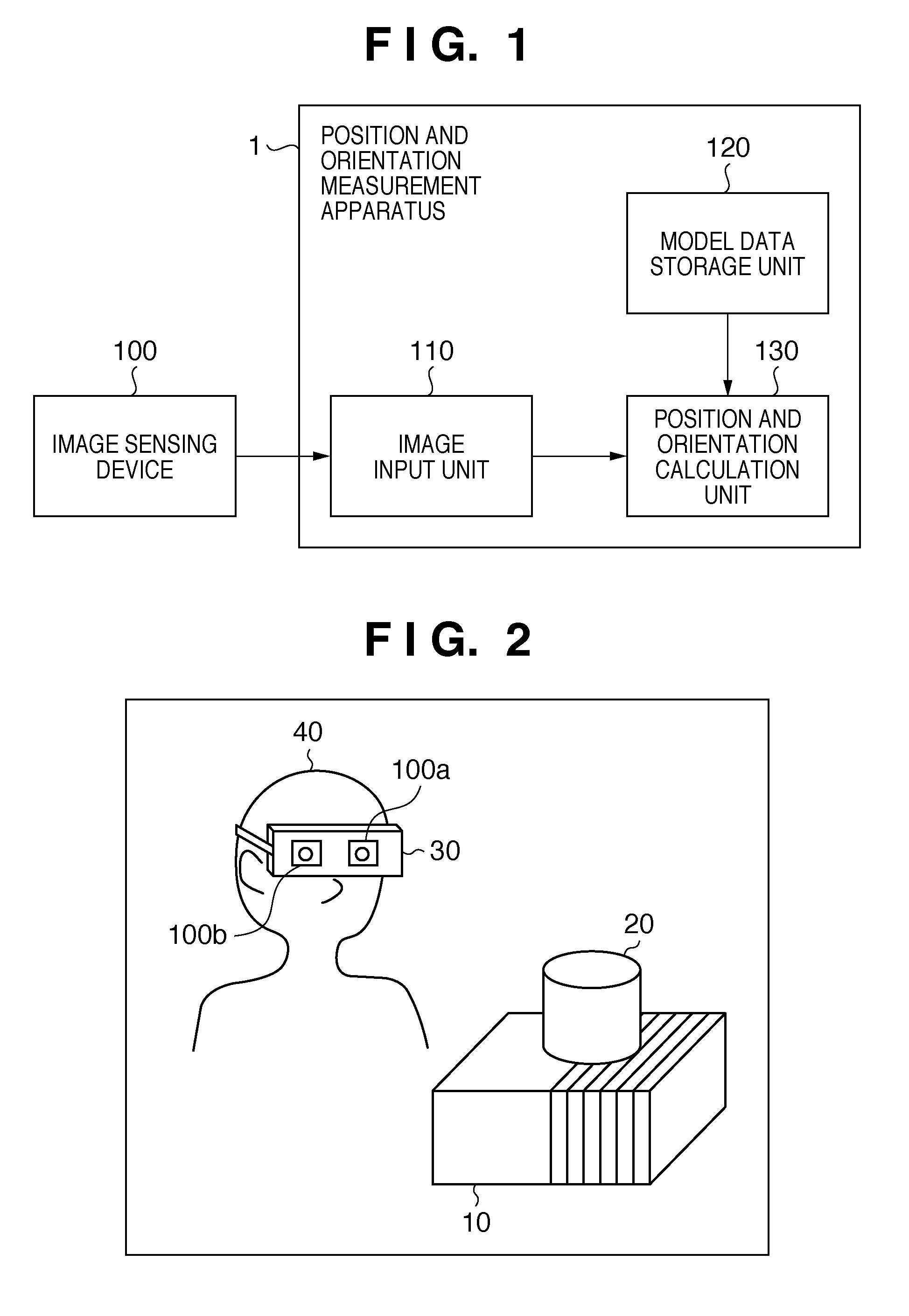
[0062]FIG. 1 is a block diagram showing an example of the functional arrangement of a system according to this embodiment. As shown in FIG. 1, the system according to this embodiment includes an image sensing device 100 and position and orientation measurement apparatus (image processing apparatus) 1. As shown in FIG. 1, the position and orientation measurement apparatus 1 has an image input unit 110, model data storage unit 120, and position and orientation calculation unit 130, and the image sensing device 100 is connected to the image input unit 110.

[0063]This embodiment has as its object to calculate the position and orientation information of a viewpoint of an image sensed by the image sensing device 100 (AR registration).

[0064]FIG. 2 is a view showing a state in which the user uses the system a...

second embodiment

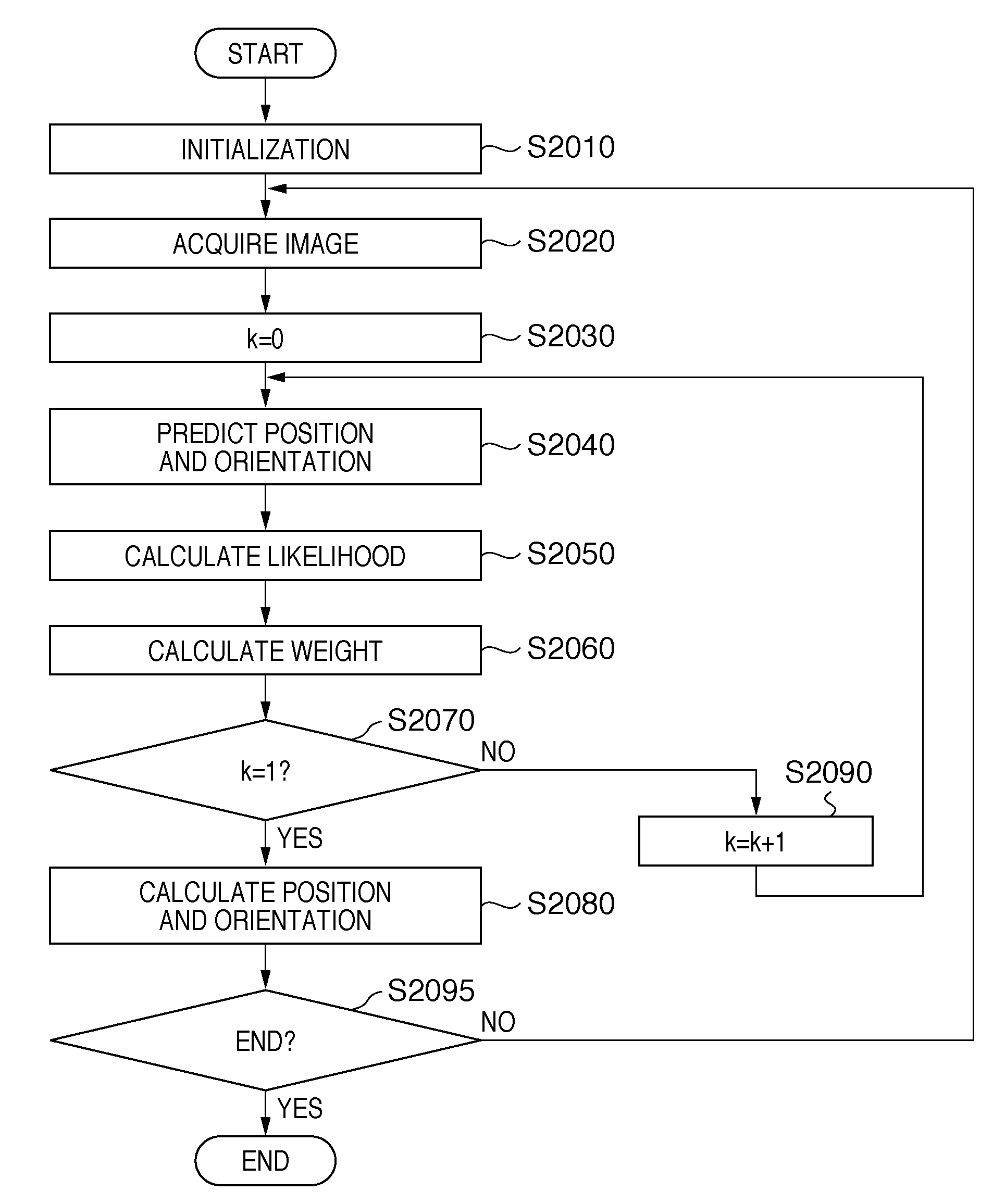
[0145]In the first embodiment, the position and orientation information of the image sensing device 100 is calculated according to the nonlinear optimization method. In this embodiment, the position and orientation information of the image sensing device 100 is calculated according to a stochastic method in place of the nonlinear optimization method. As the stochastic method used in this embodiment, a particle filter (also called CONDENSATION) described in non-patent reference 9 or 10 is used.

[0146]In the particle filer, the position and orientation information of the image sensing device 100 at a certain time t is expressed by a set of Np states (to be referred to as particles hereinafter) (p(i, t), w(i, t)) (i=1, . . . , Np). Note that p(i, t) is a state vector which expresses position and orientation information of six degrees of freedom of a particle i at the time t, and w(i, t) is a weight value for the particle i at the time t. A particle with a large weight value has high pro...

third embodiment

[0186]The position and orientation measurement apparatus 1 shown in FIG. 1 can be implemented using a general PC (personal computer).

[0187]FIG. 12 is a block diagram showing an example of the hardware arrangement of a computer which is applicable to the position and orientation measurement apparatus 1.

[0188]A CPU 1201 controls the overall computer using programs (computer programs) and data stored in a RAM 1202 and ROM 1203, and executes respective processes which are described above as those to be implemented by the position and orientation measurement apparatus 1.

[0189]The RAM 1202 has an area for temporarily storing programs and data loaded from an external storage device 1206, data externally received via an I / F (interface) 1207, and the like. Furthermore, the RAM 1202 also has a work area used when the CPU 1201 executes various processes. That is, the RAM 1202 can provide various areas as needed.

[0190]The ROM 1203 stores setting data, a boot program, and the like of the compute...


PUM


Abstract

A unit (110) acquires an image, sensed by an image sensing device (100), of a physical object having an outer appearance that can be expressed by line segments. A unit (120) stores defining data used to classify line segments configuring a 3D virtual object that simulates the outer appearance of the physical object into a plurality of groups and to define respective line segments belonging to the groups. A unit (130) selects one group from the groups one by one without any repetition. The unit (130) projects line segments which belong to the selected group onto a physical space using the defining data used to define that line segments, and the image of the physical space. The unit (130) then updates a position and orientation of the image sensing unit based on the line segments projected onto the physical space and a feature in the image of the physical object.

Description

BACKGROUND OF THE INVENTION[0001]1. Field of the Invention[0002]The present invention relates to a technique for calculating position and orientation information of a viewpoint of an image using the image.[0003]2. Description of the Related Art[0004]In recent years, the studies of information presentation techniques called Mixed Reality techniques (to be referred to as MR techniques hereinafter) have been extensively made. Of the MR techniques, the studies of an Augmented Reality technique (to be referred to as an AR technique hereinafter) which superimposes and displays information of a virtual space on a physical space have been especially extensively made. As a typical information presentation apparatus based on the AR technique, a video see-through Head Mounted Display (to be abbreviated as HMD hereinafter) is known. The video see-through HMD incorporates a camera for sensing an image of the physical space. On the image of the physical space sensed by this camera, a virtual obje...

Claims


Application Information

Patent Timeline
Patent Type & Authority Applications(United States)
IPC IPC(8): G06T15/20G01B11/00G06T7/60
CPCG02B27/017G02B2027/0138G02B2027/014G02B2027/0187G06T19/006G06T7/0042G06T7/0083G06T2207/10016G06F3/011G06T7/12G06T7/73
Inventor KOTAKE, DAISUKEUCHIYAMA, SHINJI
Owner CANON KK
Why Eureka
Try Eureka