
Inspection head supporting structure in surface inspecting apparatus and surface inspecting apparatus

a technology of inspection head and supporting structure, which is applied in the direction of instruments, measurement devices, scientific instruments, etc., to achieve the effects of reducing the burden of centering work in removing, installing or replacing the inspection head, improving the accuracy of the shake in the rotation of the inspection head, and reducing the looseness of the bearings

Active Publication Date: 2009-10-22
NAGANO AUTOMATION
View PDF0 Cites 28 Cited by
  • Summary
  • Abstract
  • Description
  • Claims
  • Application Information

AI Technical Summary

Benefits of technology

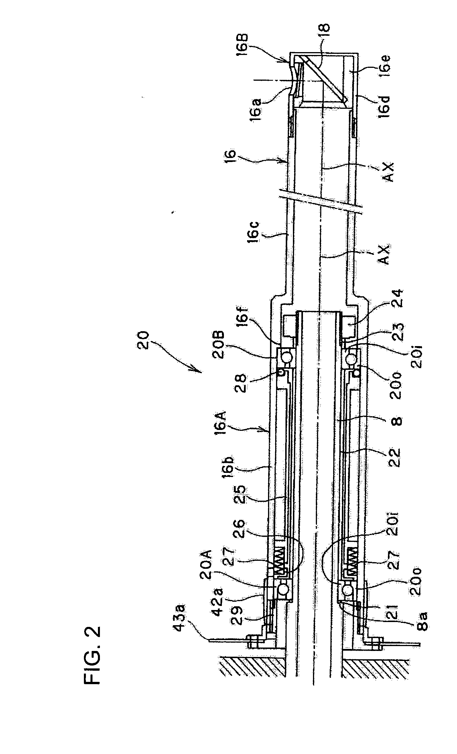
[0021]According to the above support structure, the inspection head is rotatably supported by a pair of bearings which are able to burden a radial load and a unidirectional axial load, and moreover, a preload pressure is applied to each of these bearings. Thus, the precision of the shake in rotation of the inspection head can be improved by reducing the looseness of the bearings. Since the inspection head is integrally removable from and installable to the bearings, after installing the bearing fitting part atop of the bearings without removing the bearing fitting part of the inspection head and the main shaft part, it is not necessary to do a centering work between the bearing fitting part and the main shaft part. Accordingly, the burden of the centering work in removing and installing or in replacing the inspection head can be reduced or cleared. Furthermore, the ring of elastic material is brought by the force of the spring device into close contact with the inner circumference of the bearing fitting part and the outer race of one of the bearings, so that a friction force is exerted between these contact surfaces. Thus, even in increasing the acceleration or the deceleration of the rotation of the inspection head, the slip between the bearing fitting part and the outer races of the bearing is hard to be generated. In this way, by suppressing the wear of the inner surface of the bearing fitting part due to the slip and by suppressing the temporal degradation of the precision of the shake in rotation, a high precision of the shake in rotation can be maintained over a long time. Furthermore, by increasing the acceleration and the deceleration of rotation, and thus by reducing the time required for the inspection, inspection efficiency can be improved. Moreover, according to the above surface inspecting apparatus, since the holder of the optical path changing device is removable from and installable to the head main body in the inspection head, only the holder can be removed and replaced in replacing the optical path changing device without removing the head main body attached to the drive device. Thus, the optical path changing device can be cleaned and replaced easily at a low cost.

Problems solved by technology

Moreover, when the optical path changing device is damaged or when an optical path changing device arranged to fit the inclination of a tapered hole is necessary to inspect the inner surface of the tapered hole, the entire inspection head is replaced.

Method used


Image

  • Inspection head supporting structure in surface inspecting apparatus and surface inspecting apparatus
  • Inspection head supporting structure in surface inspecting apparatus and surface inspecting apparatus
  • Inspection head supporting structure in surface inspecting apparatus and surface inspecting apparatus

Examples


first embodiment

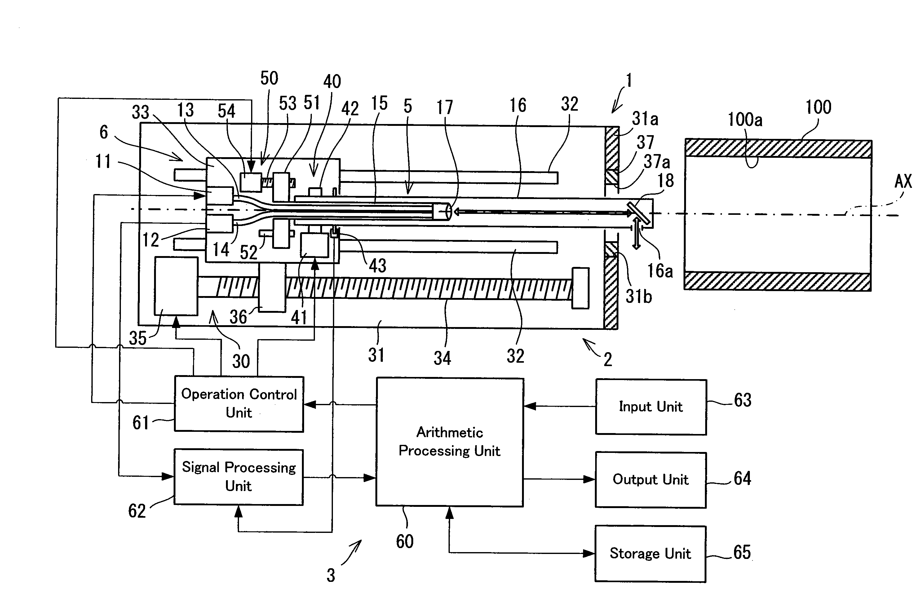
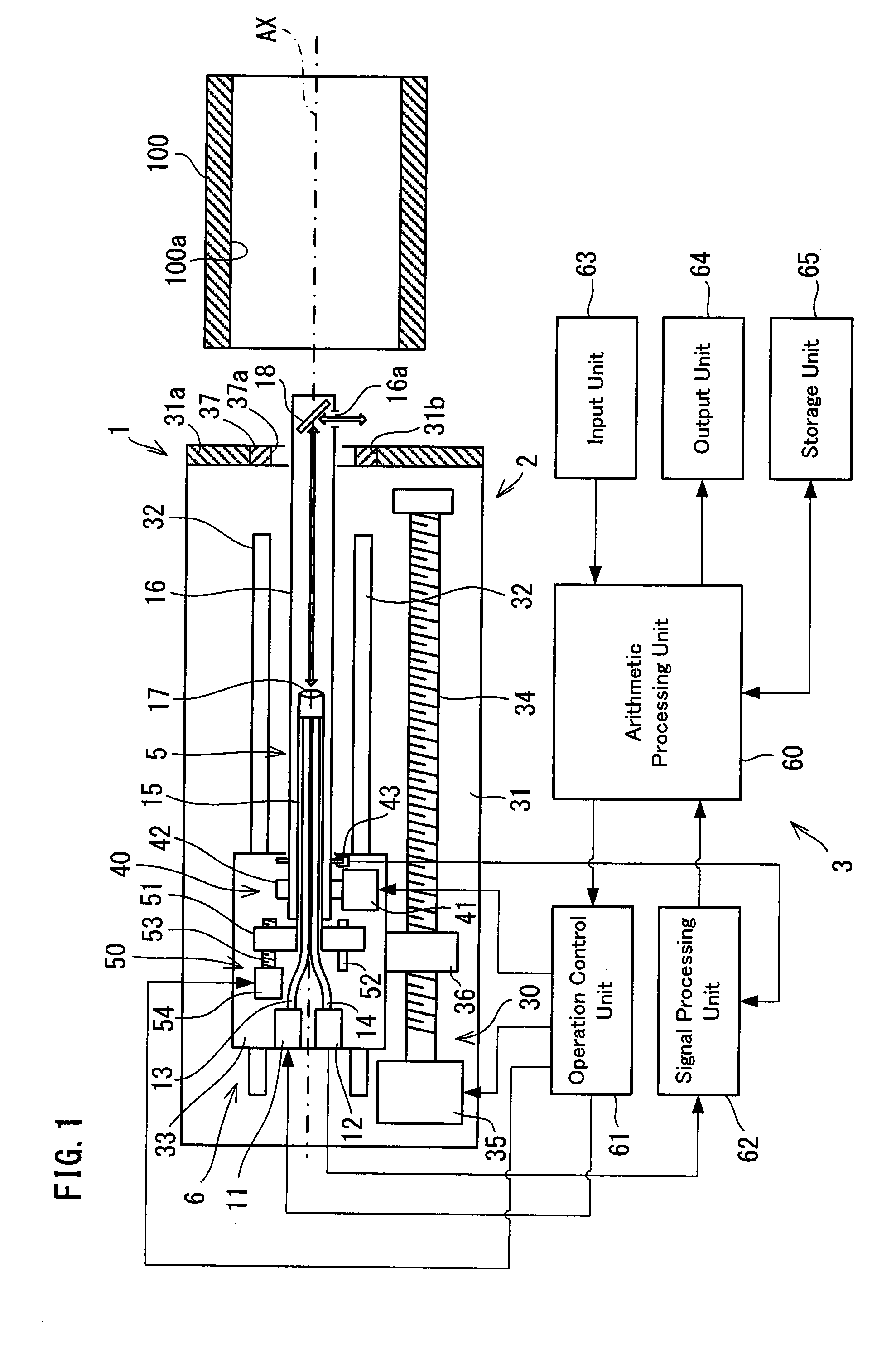
[0030]FIG. 1 shows a schematic structure of a surface inspecting apparatus in the present invention. The surface inspecting apparatus 1 is a device suitable for inspecting a cylindrical inner peripheral surface 100a provided to an inspection object 100, and includes an inspection mechanism 2 for executing inspection, and a control unit 3 for executing the operation control of the inspection mechanism 2 and for processing measuring results by the inspection mechanism 2 or the like. Furthermore, the inspection mechanism 2 includes a detection unit 5 serving as the detection device for projecting an inspection light to the inspection object 100 and for receiving a reflection light from the inspection object 100, and a drive unit 6 for making the detection unit 5 to work in a prescribed manner.

[0031]The detection unit 5 includes a laser diode 11 (it will be referred as LD in the following) serving as the light source of an inspection light, and a photo detector 12 (it will be referred a...

second embodiment

[0054]FIG. 3 shows a schematic structure of a surface inspecting apparatus in the present invention. The surface inspecting apparatus 101 is a device suitable for inspecting a cylindrical inner peripheral surface 200a provided to an inspection object 200, and includes an inspection mechanism 102 for performing inspection, and a control unit 103 for executing the control operation of the inspection mechanism 102 and the processing of the measuring results by the inspection mechanism 102 or the like. Furthermore, the inspection mechanism 102 includes a detection unit 105 which projects an inspection light to the inspection object 200 and receives the reflection light from the inspection object 200, and a drive unit 106 which makes the detection unit 105 to work in a prescribed manner.

[0055]The detection unit 105 includes a laser diode (LD) 111 serving as the light source of the inspection light, a photo detector 112 (it will be referred as PD in the following) which receives the refle...


PUM


Abstract

A pair of angular contact bearings 20A, 20B are disposed between a bearing house 16b of an inspection head 16 and a head supporting tube 8, and a spacer 25 and a spring bearing ring 26 are disposed between outer races 20o of the bearings 20A, 20B. The spacer 25 and the spring bearing ring 26 are urged by a coil spring 27 toward the side of the outer race 20o. An O-ring 28 is disposed between the spacer 25 and the outer race 20o of the bearing 20B, and the outer circumference of the O-ring is brought into closely contact with the inner circumference of the bearing house 16b. The outer races 20o are constrained by a step part 16f in the bearing house 16b and an end cap 29 screwed into the inspection head 16. Removing the end cap 29 makes it possible to take out the bearing housing 16b and a main shaft part 16c integrally from atop of the bearings 20A, 20B.

Description

TECHNICAL FIELD[0001]The present invention relates to an inspection head supporting structure in a surface inspecting apparatus, which irradiates an inspection light from an inspection head to an inspection object thereby inspecting the surface of the inspection object, or it relates to a surface inspecting apparatus of inspecting the surface condition of an inspection object.RELATED ART[0002]As an apparatus of inspecting the inner peripheral surface of a cylindrical inspection object, a surface inspecting apparatus is known which drives out a hollow shaft-like inspection head in the axial direction of the inspection head with rotating the inspection head around its axis, The surface inspecting apparatus inserts the inspection head into the interior of the inspection object, irradiates a laser beam serving as an inspection light from the outer circumference of the inspection head, step scans the inner peripheral surface of the inspection object from one end to the other end along th...

Claims


Application Information

Patent Timeline
IPC IPC(8): G01N21/55
CPCG01N21/954G01N21/55
Inventor HORIUCHI, KAZUHIROARITO, TATSUNARI
Owner NAGANO AUTOMATION
Learn More