Laser drive circuit and use
a laser diode and drive circuit technology, applied in the field of laser drive circuits, to achieve the effect of improving the drive circuit of the laser diod
- Summary
- Abstract
- Description
- Claims
- Application Information
AI Technical Summary
Benefits of technology
Problems solved by technology
Method used
Image
Examples
Embodiment Construction
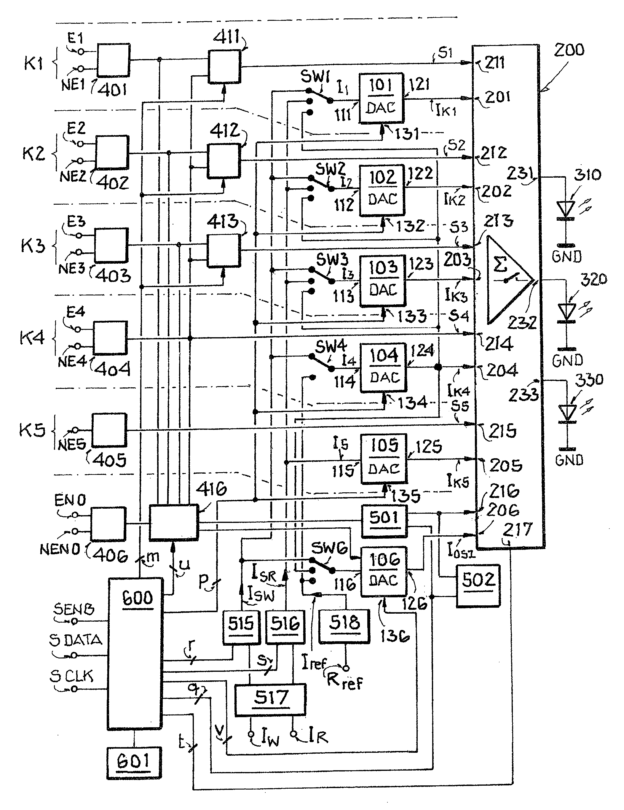
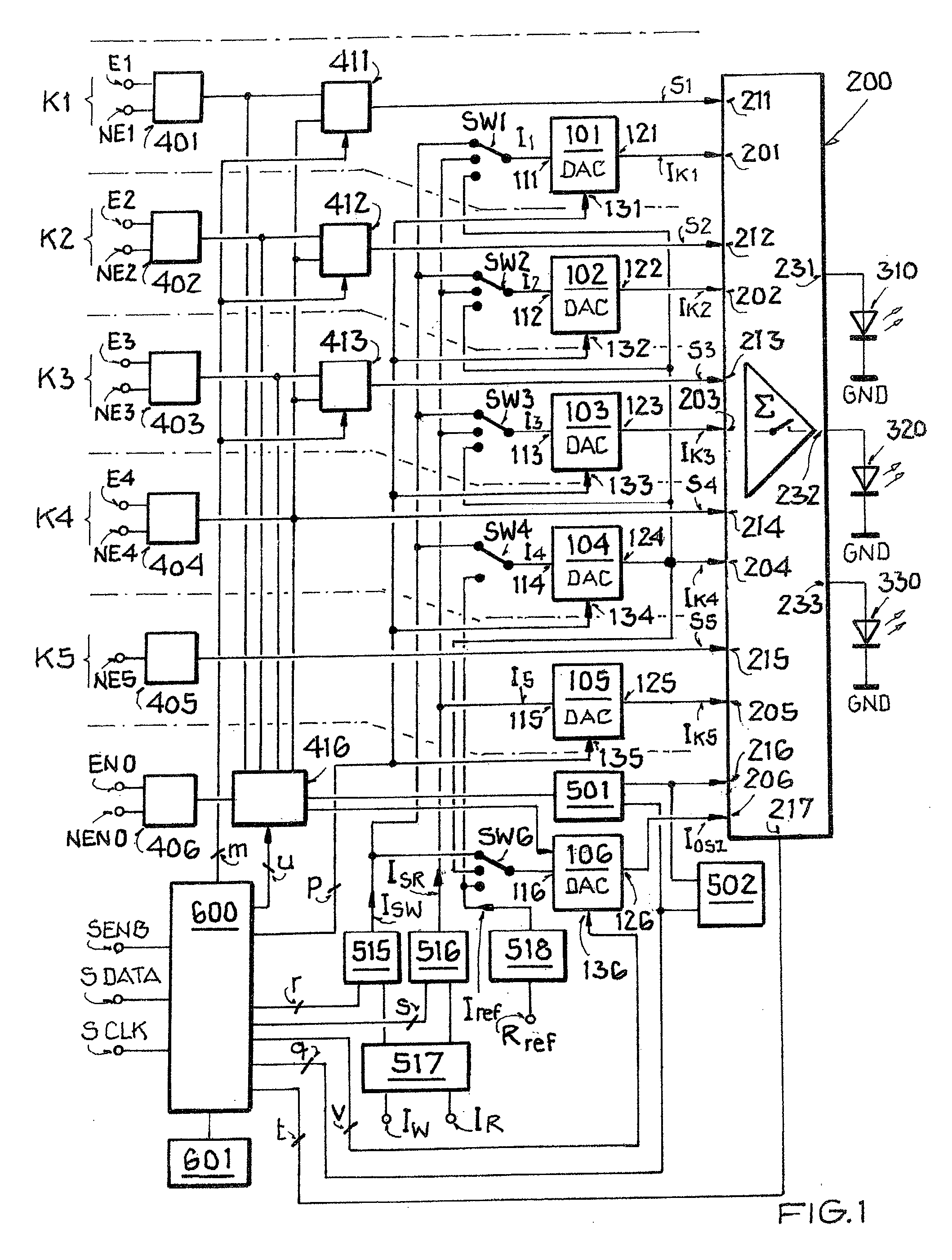
[0040]FIG. 1 shows a schematic block diagram of a laser drive circuit. Also shown by way of example are three laser diodes 310, 320, 330, which are connected to outputs 231, 232, and 233 of a switching amplifier device 200 of the laser drive circuit. The exemplary embodiments with current inputs, current outputs, and current amplifications will be described hereinafter as a preferred exemplary embodiment.
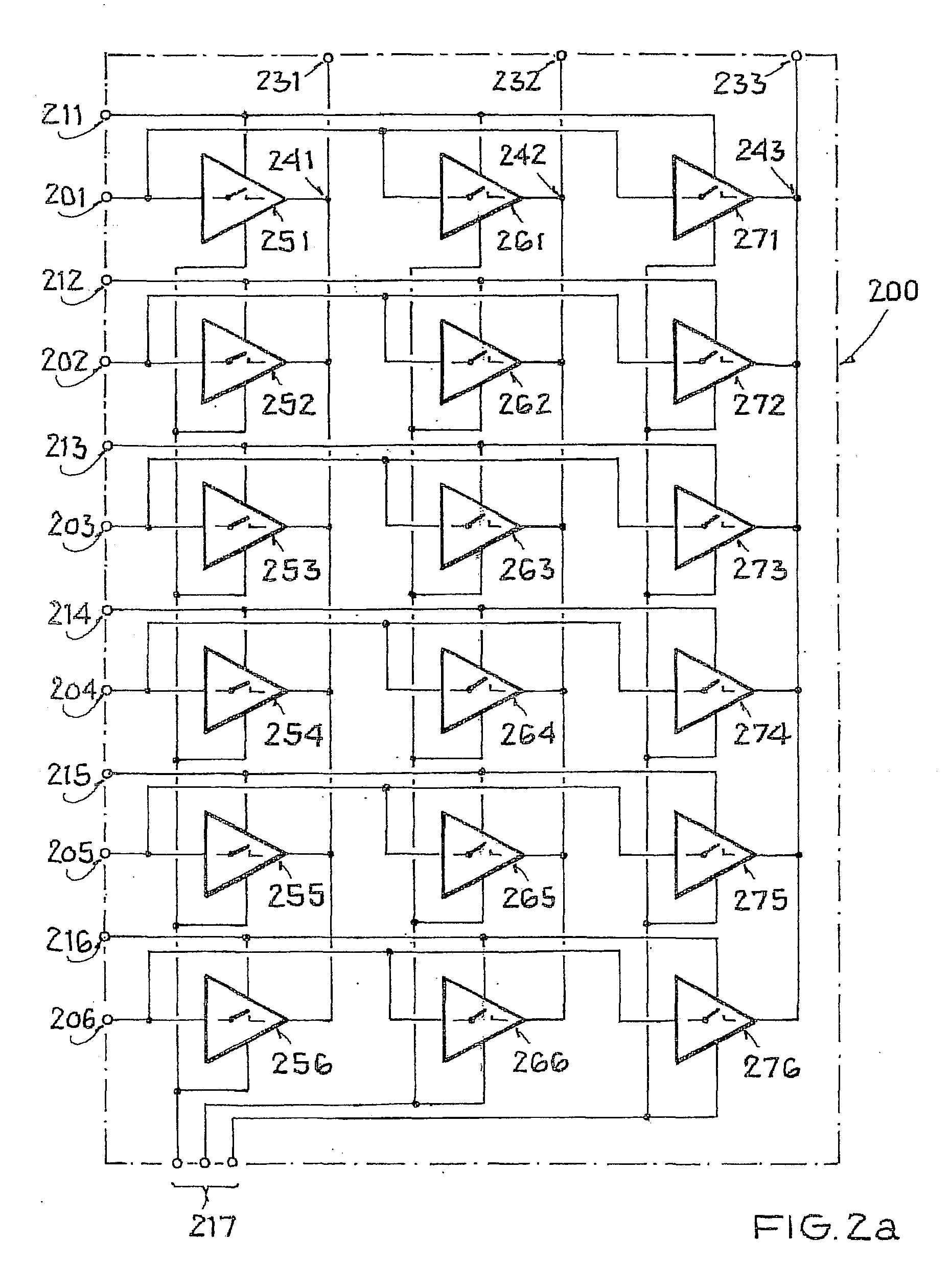
[0041]According to the exemplary embodiment of FIG. 1, switching amplifier device 200 has current inputs 201, 202, 203, 204, 205, and 206; here, switching amplifier device 200 is formed and set up to switch currents flowing through inputs 201, 202, 203, 204, 205, and 206, to amplify them and to sum them, and to provide them at one of outputs 231, 232, 233 to the respective laser diode 310, 320, 330. To switch input currents Ik1, Ik2, Ik3, Ik4, Ik5, and IOSZ at current inputs 201, 202, 203, 204, 205, and 206, switching amplifier device 200 has a number of corresponding switch inputs ...
PUM
| Property | Measurement | Unit |
|---|---|---|
| current | aaaaa | aaaaa |
| oscillator frequency | aaaaa | aaaaa |
| wavelength ranges | aaaaa | aaaaa |
Abstract
Description
Claims
Application Information
 - R&D
- Intellectual Property
- Life Sciences
- Materials
- Tech Scout
- Unparalleled Data Quality
- Higher Quality Content
- 60% Fewer Hallucinations
Browse by: Latest US Patents, China's latest patents, Technical Efficacy Thesaurus, Application Domain, Technology Topic, Popular Technical Reports.
© 2025 PatSnap. All rights reserved.Legal|Privacy policy|Modern Slavery Act Transparency Statement|Sitemap|About US| Contact US: help@patsnap.com


