Mammography system and method for its operation

a technology of mammography and operation method, applied in the field of mammography, can solve the problems of deteriorating image quality, inability to use images, and inability to prevent breast movement by compression members,

Active Publication Date: 2009-10-22
GENERAL ELECTRIC CO
View PDF11 Cites 58 Cited by
  • Summary
  • Abstract
  • Description
  • Claims
  • Application Information

AI Technical Summary

Benefits of technology

[0039]The monitoring means, the information presenting means, the user interface are provided in a removable module able to cooperate with a base of the system to ensure their functions.

Problems solved by technology

The compression exerted by the compression members on the breast does not, however, prevent the breast from moving as and when the successive X-ray images are taken.
Breast movements during image acquisition create artefacts and localization errors on the images, which may lead to deterioration of image quality and even make images unusable.
If the examination lasts longer, breathing and involuntary movements are difficult to prevent.
If the breast has moved between two images, there is no blur but shifting of the breast between the two images which may give rise to problems during post-processing of the images, thereby distorting the three-dimensional reconstruction of the breast.
The compensation or correction of an image by calculation, in the event of breast movement, is cumbersome and complicated to apply.
In practice it is difficult to implement automatic image or image data analysis that is satisfactory.
Additionally, image correction is most often oversized compared with the actual needs of a mammography technician.
Finally, control over the speed of the motor moving the breast compression plate is sufficient to achieve proper breast compression before taking any images, but does not prevent the breast from moving once the motor is stopped and the compression plate has been immobilized.

Method used


Image

  • Mammography system and method for its operation
  • Mammography system and method for its operation
  • Mammography system and method for its operation

Examples


Embodiment Construction

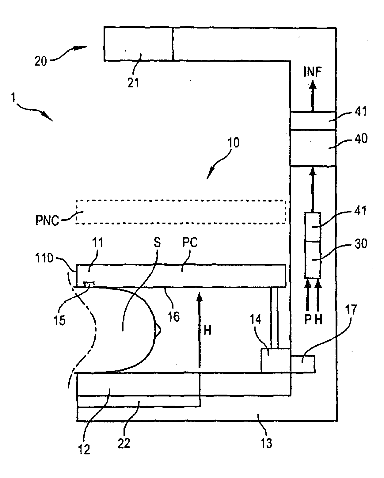
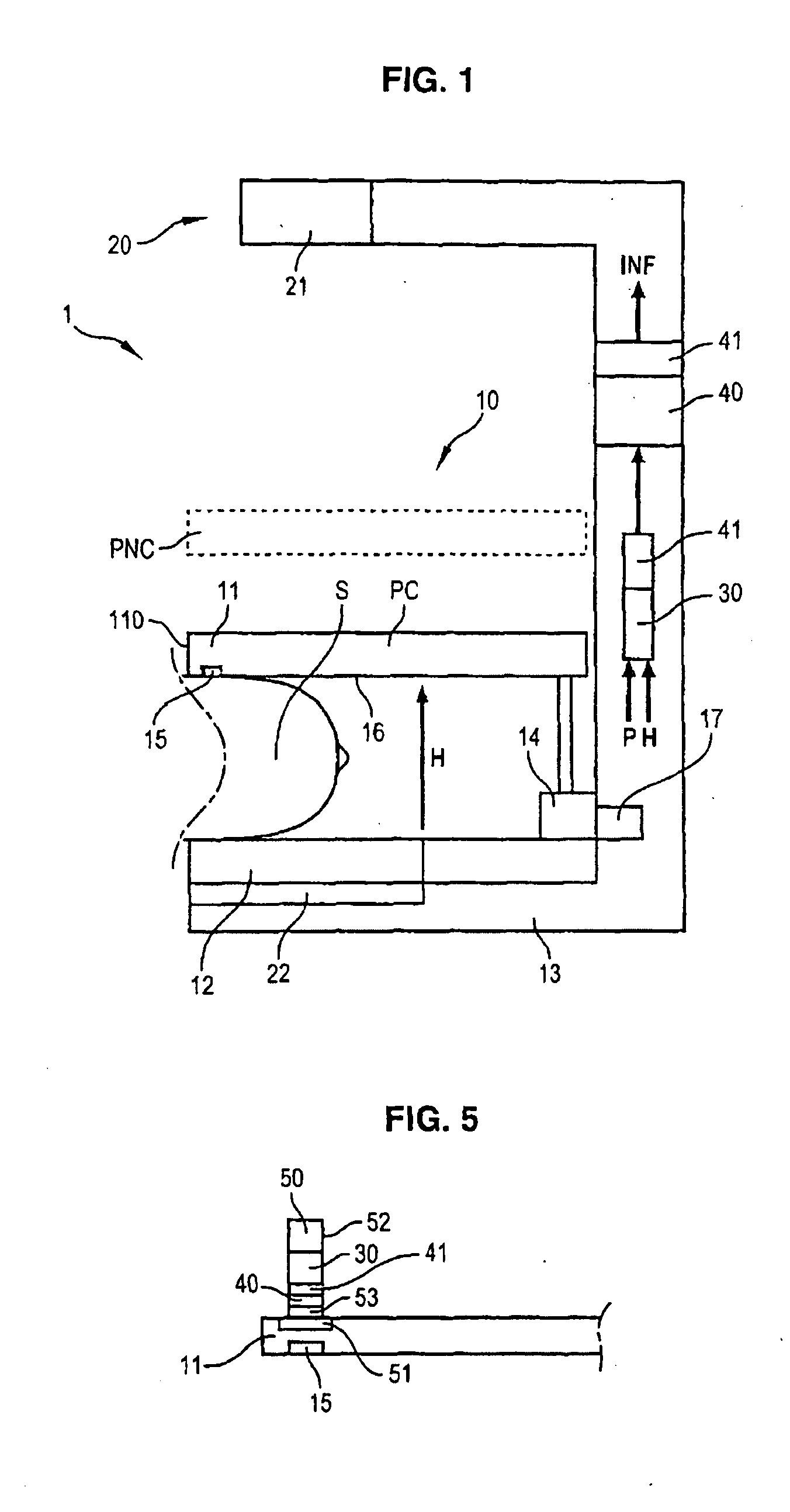
[0054]In FIG. 1, the mammography system 1 comprises a breast compression device 10, comprising a first compression member 11 and a second compression member 12. For example, in the case shown in FIG. 1, the compression member 12 acts as support means for the breast S and is therefore a lower member, whilst member 11 is the upper member located above the breast.

[0055]The system 1 comprises a system 20 to acquire X-ray images of the breast, comprising firstly an X-ray source 21 and secondly a plate or any other means 22 to record an X-ray image of the breast S, the image recording means 22 being located on the other side of the breast S relative to the source 21.

[0056]The first member 11 lies away from the second member 12 in a direction H. The first member 11 and the second member 12 are mobile relative to one another. For example, member 11 is mobile relative to member 12 attached to a fixed frame 13 of the system 1, carrying the source 21. The source 21 is provided for example on t...


PUM


Abstract

A mammography system including a compression device, comprising two compression members to compress a breast, a sensor to sense the pressure exerted by the breast on one of the members and/or a device to determine the distance between the two members, an X-ray image acquisition system, means to adjust an initial position of the members. The system further comprises means to monitor variations in pressure and/or variations in thickness relative to their initial value, for an estimation of the risk of breast movement. The system further comprises means to present the user with information signalling breast movement, in relation to the estimation.

Description

CROSS-REFERENCE TO RELATED APPLICATIONS[0001]This application claims priority under 35 U.S.C. §119(a)-(d) or (f) to prior-filed, co-pending French patent application serial number 0852595, filed on Apr. 17, 2008, which is hereby incorporated by reference in its entiretySTATEMENT REGARDING FEDERALLY SPONSORED RESEARCH OR DEVELOPMENT[0002]Not ApplicableNAMES OF PARTIES TO A JOINT RESEARCH AGREEMENT[0003]Not ApplicableREFERENCE TO A SEQUENCE LISTING, A TABLE, OR COMPUTER PROGRAM LISTING APPENDIX SUBMITTED ON COMPACT DISC[0004]Not ApplicableBACKGROUND OF THE INVENTION[0005]1. Field of the Invention[0006]The field of the invention relates to mammography.[0007]2. Description of Related Art[0008]In the area of application of an embodiment of the invention, one or more X-rays of a breast are taken, e.g. to investigate the breast tissue with a view to detecting the presence of tumours for example.[0009]For this purpose, a device is used to compress the breast to be X-rayed between two compre...

Claims


Application Information

Patent Timeline
Patent Type & Authority Applications(United States)
IPC IPC(8): A61B6/04
CPCA61B5/6843A61B5/6844A61B5/6886A61B5/721A61B6/583A61B6/0414A61B6/502A61B6/527A61B6/025
Inventor IORDACHE, RAZVAN GABRIELABELLAN-MARTINEZ, JOSE
Owner GENERAL ELECTRIC CO
Why Eureka
Try Eureka