Method and system for managing shared random numbers in secret communication network

Active Publication Date: 2009-10-22
NEC CORP
View PDF4 Cites 59 Cited by
  • Summary
  • Abstract
  • Description
  • Claims
  • Application Information

AI Technical Summary

Benefits of technology

[0024]According to the present invention, random number sequences can be effici

Problems solved by technology

The Internet is an economic and social infrastructure over which various kinds of data are exchanged, and therefore it is an important issue to provide for preventive measures to protect data flowing over the network from risks of eavesdropping beforehand.
This method is used to distribute a cryptographic key for the common key cryptography because it is not suitable for high-speed processing.
Security according to these methods depends on the fact that an enormous amount of calculation is required for cryptanalysis.
However, conventional technologies place importance only on the generation of shared information such as a cryptographic key, and the management of shared information even considering the consumption thereof has hardly been performed.
In addition, key generation rates are not uniform among nodes in general because the key generation rate, at which a cryptographic key is generated through the key gen

Method used


Image

  • Method and system for managing shared random numbers in secret communication network
  • Method and system for managing shared random numbers in secret communication network
  • Method and system for managing shared random numbers in secret communication network

Examples


Example

2. FIRST EXAMPLE

2.1) Configuration

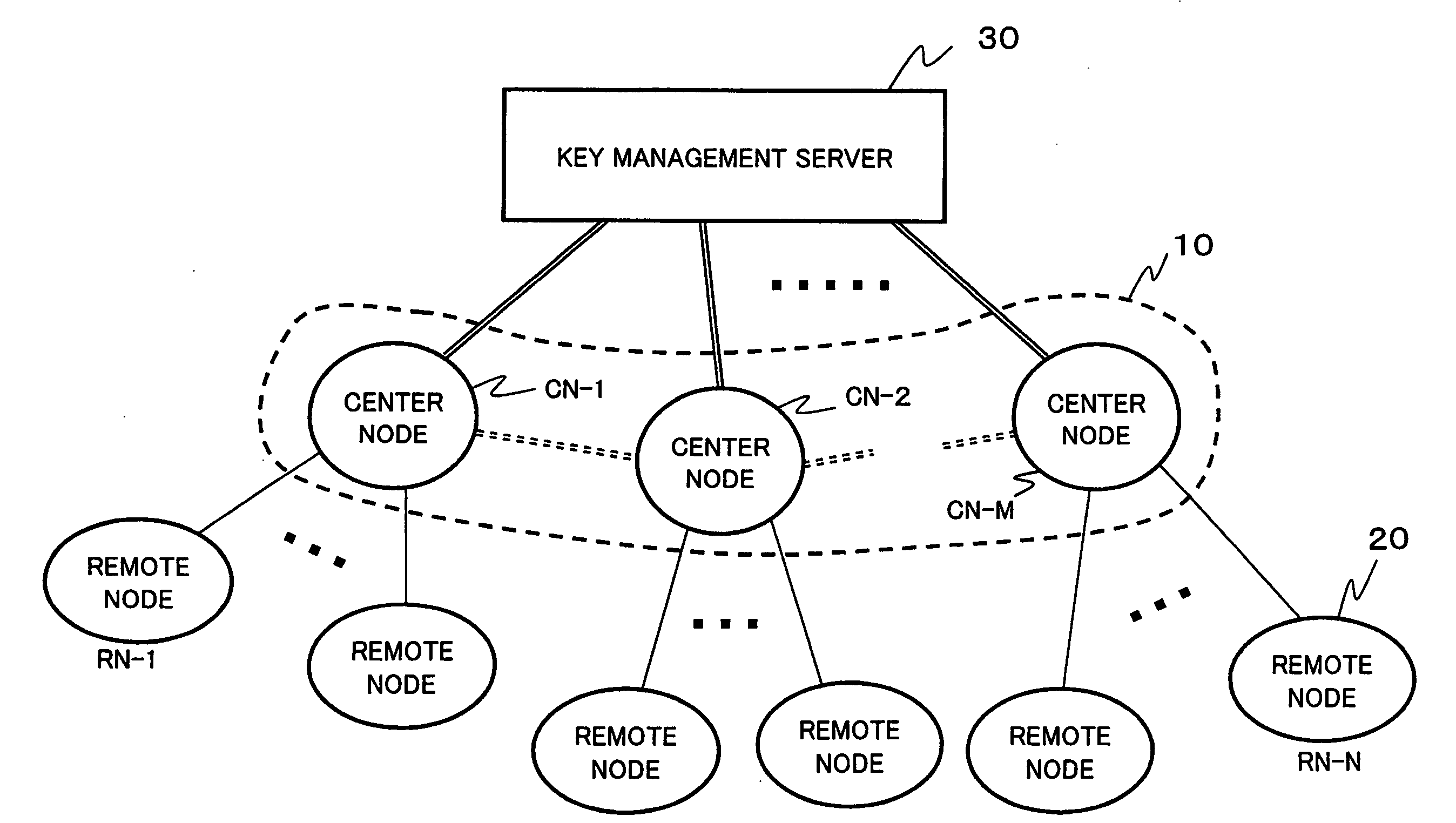
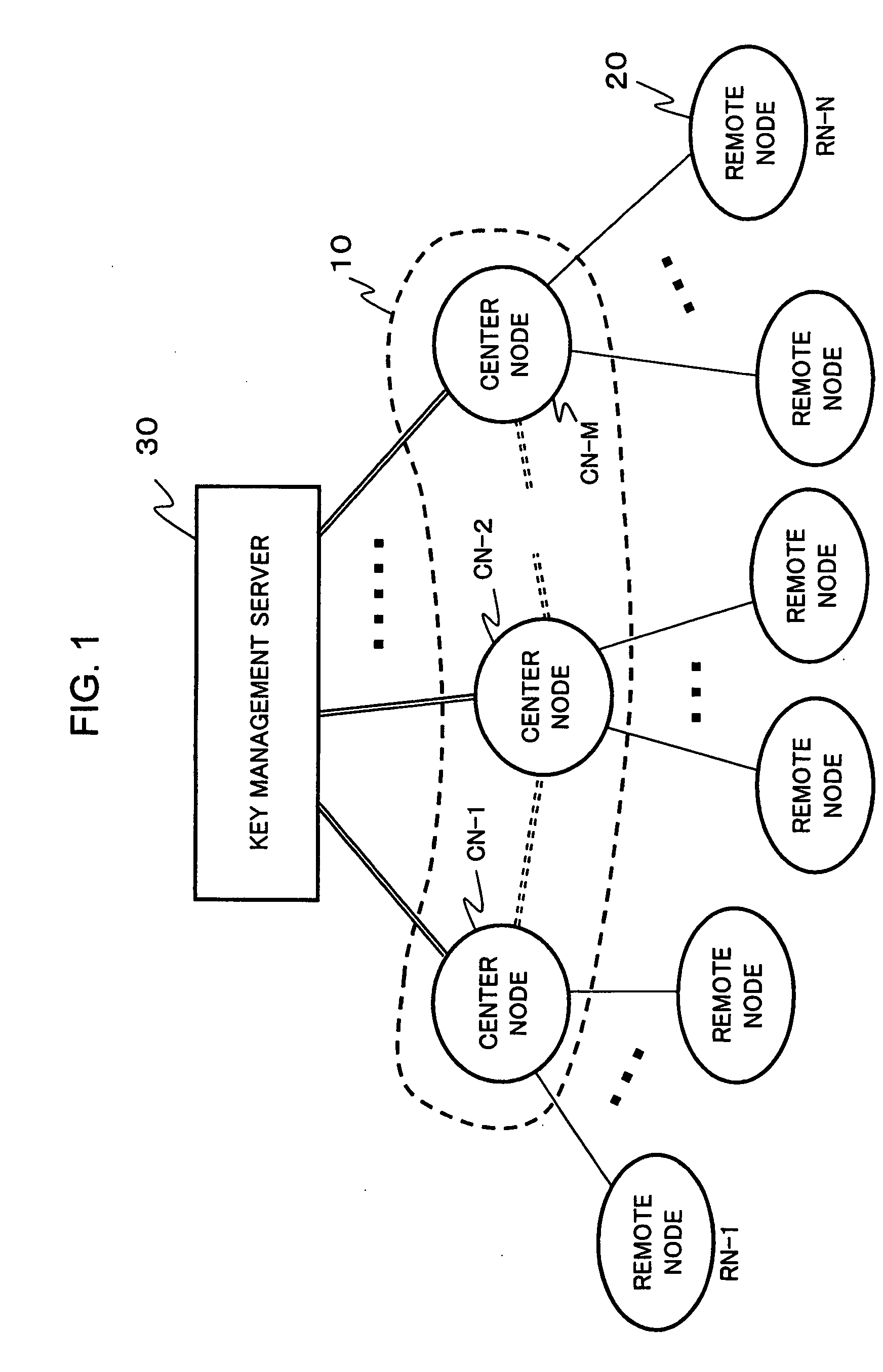
[0064]FIG. 5 is a block diagram showing a schematic configuration and structure of a quantum key distribution network according to a first example of the present invention. Here, shown is selected part of the network shown in FIG. 1, in which each of N remote nodes RN-1 to RN-N is connected to a center node CN through optical fiber, and the generation and sharing of a quantum key, as well as cipher communication using the quantum key, are performed between each remote node RN-i and the center node CN.

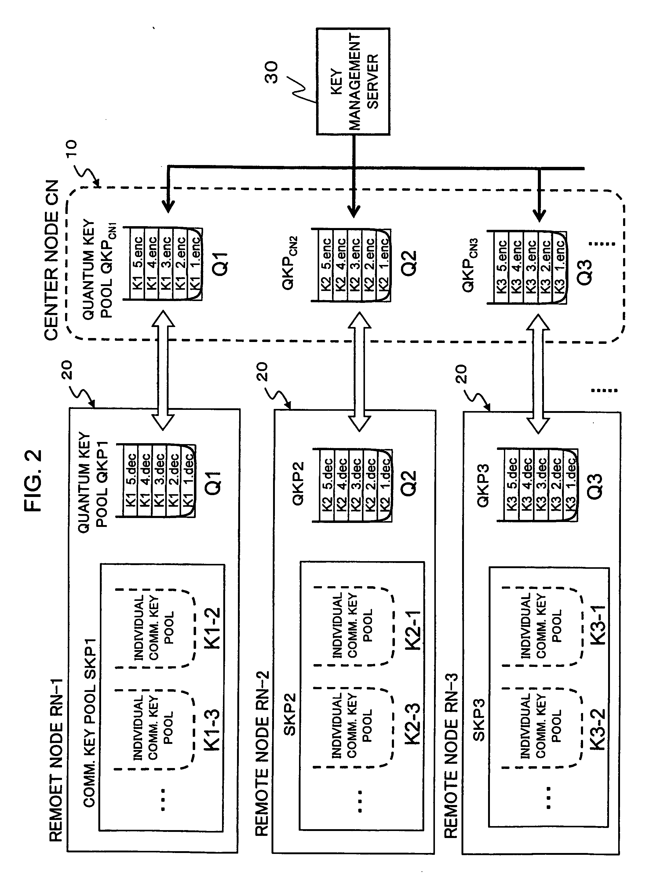
[0065]The remote nodes RN-1 to RN-N have similar configurations, each including a quantum channel unit 201, a classical channel unit 202, a control section 203 controlling these units, and a key memory 204 for storing keys.

[0066]The respective key memories 204 of the remote nodes RN-1 to RN-N are provided with quantum key pools QKP1 to QKPN, respectively, in which quantum keys Q1, Q2, . . . , QN generated and shared between each remote node RN-i and th...

Example

3. SECOND EXAMPLE

[0103]FIG. 10 is a block diagram showing a schematic configuration of a secret communication network according to a second example of the present invention. Here, shown is selected part of the network shown in FIG. 1. With respect to a QKD network A (QKD-NW-A), N remote nodes and a center node constitute a 1:N network. Each of the N remote nodes RN-A1 to RN-AN is connected to the center node CNa through optical fiber, and the generation and sharing of a cryptographic key, as well as cipher communication using the cryptographic key, are performed between each remote node and the center node CNa.

[0104]The configurations of each remote node RN-A and the center node CNa are similar to those shown in FIG. 5. In FIG. 10, for simplification, the quantum channel units and classical channel units as well as the control sections of the remote nodes are omitted.

[0105]On the other hand, with respect to a QKD network B (QKD-NW-B), M remote nodes and a center node constitute a 1...


PUM


Abstract

A method for managing shared random numbers in a secret communication network including at least one center node and a plurality of remote nodes connected to the center node, includes: sharing random number sequences between the center node and respective ones of the plurality of remote nodes; when performing random numbers sharing between a first remote node storing a first random number sequence shared with the center node and a second remote node storing a second random number sequence shared with the center node, distributing a part of the second random number sequence from the center node to the first remote node; and sharing the part of the second random number sequence between the first remote node and the second remote node.

Description


Claims


Application Information

Patent Timeline
Owner NEC CORP
Why Eureka
Try Eureka