Ducted fan with inlet vanes and deswirl vanes

Inactive Publication Date: 2009-10-22
MINEBEA CO LTD
View PDF23 Cites 36 Cited by
  • Summary
  • Abstract
  • Description
  • Claims
  • Application Information

AI Technical Summary

Benefits of technology

[0010]Many benefits are achieved by applying embodiments of the present invention. Certain embodiments of the invention provide a ducted fan apparatus with a unique combination of a single rotating impeller disposed between two sets of stationary vanes. This can be configured to operate at relative high rotational speeds of 30,000 rpm or higher compared to conventional cooling fan running at speed of 15,000 rpm or lower. Additionally, the ducted fan configured according to certain embodiment of the present invention also advantageously differs from convention ducted fans with either a single set of stationary vanes at upstream or downstream of an rotating impeller. The advantage relies on the improved p

Problems solved by technology

The flow of air processed by such a conventional ducted fan is deficient in the flow's directional guidance and is lacking in output capacity

Method used


Image

  • Ducted fan with inlet vanes and deswirl vanes
  • Ducted fan with inlet vanes and deswirl vanes
  • Ducted fan with inlet vanes and deswirl vanes

Examples


Embodiment Construction

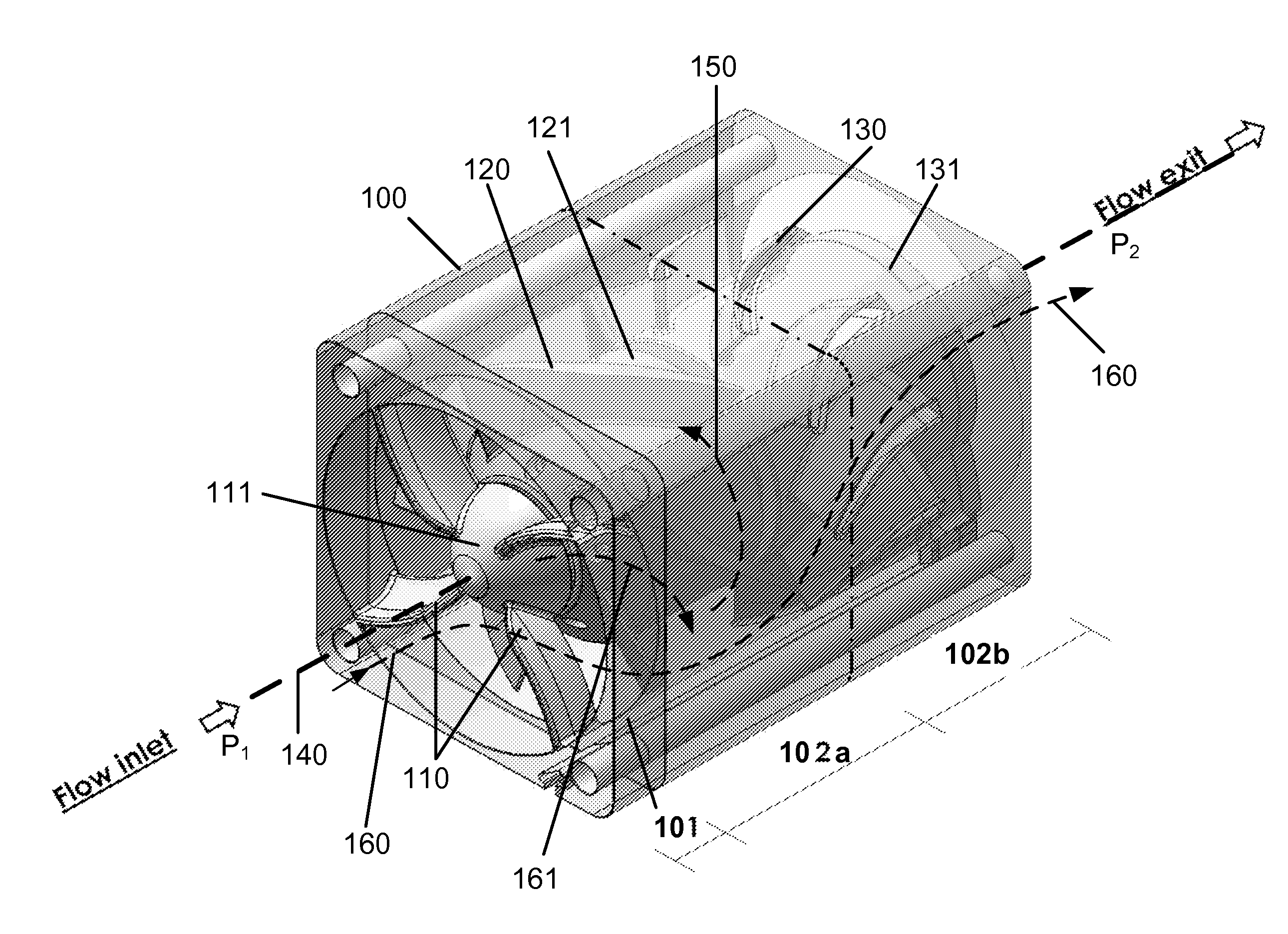
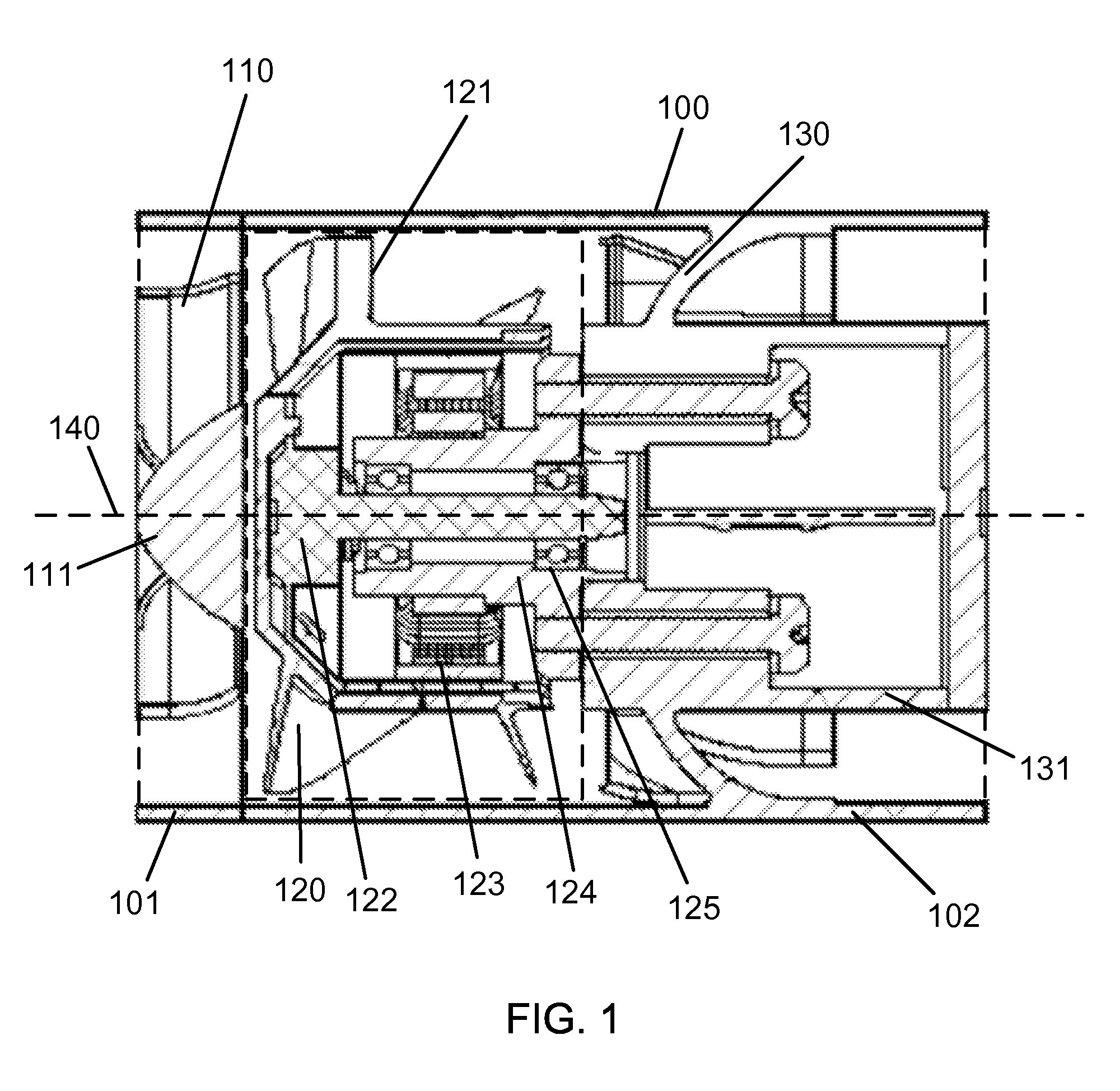
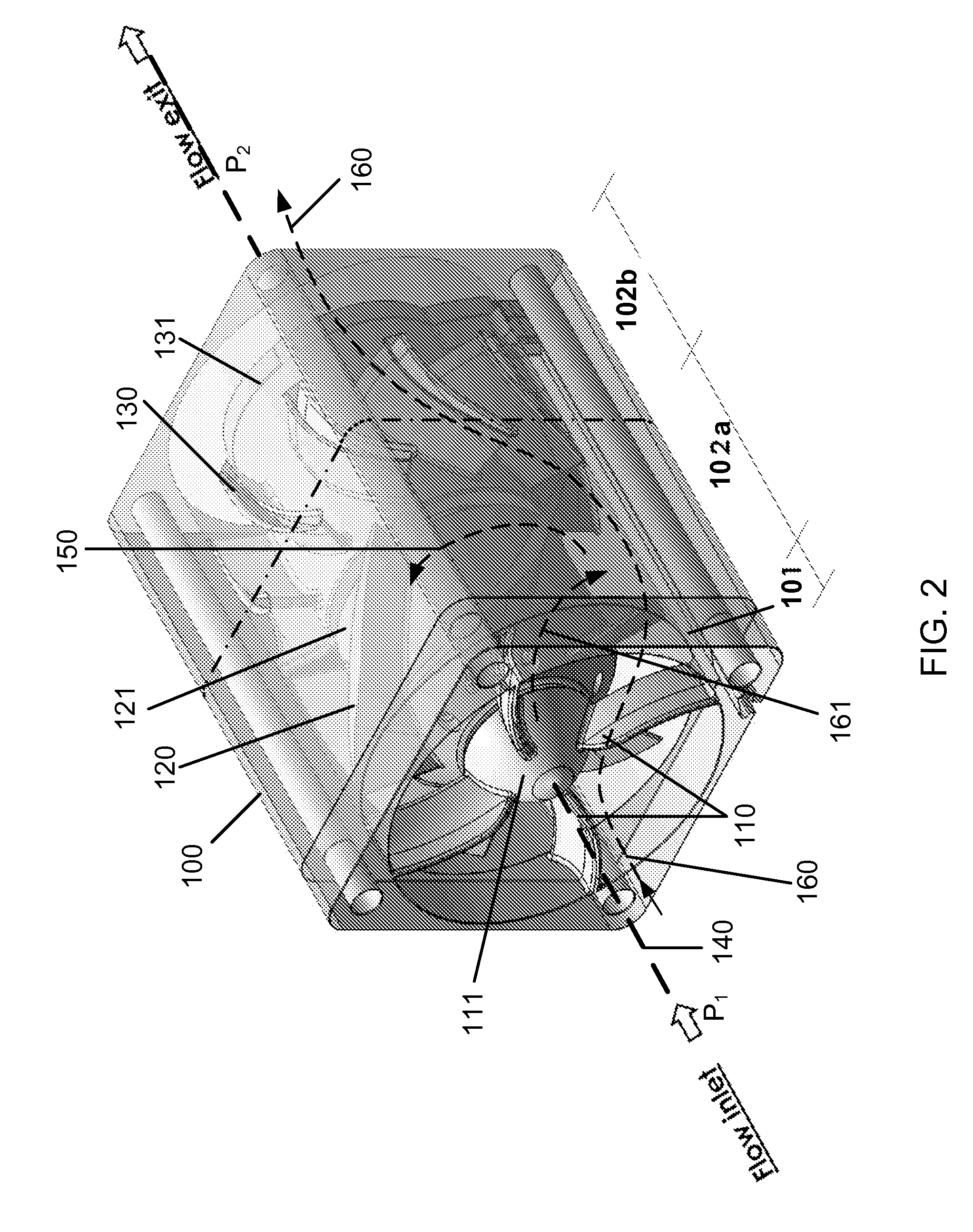
[0016]FIG. 1 is a schematic cross-sectional view of a ducted fan apparatus according to an embodiment of the present invention. This diagram is merely an example, which should not unduly limit the scope of the claims herein. One of ordinary skill in the art would recognize many variations, alternatives, and modifications. As shown, a fan apparatus includes three sets of blades sequentially disposed within a ducted housing 100 which has an interior surface enclosing an interior volume of space. In one embodiment, the ducted housing 100 includes a first section 101 and a second section 102 and is substantially symmetric around an axis of rotation 140. In one example, the first section 101 is located upstream of the second section 102 when the ducted fan apparatus is used for processing a flow of fluid including air. The interior volume of space is a cylindrical shape around the axis of rotation 140. In another example, the interior volume of space within the first section can have a d...


PUM


Abstract

A fan apparatus includes a ducted housing with an axis of rotation including a first section and a second section. The fan apparatus further includes a first plurality of vanes being radially coupled within the first section and a second plurality of vanes being radially coupled within the second section. Additionally, the fan apparatus includes an impeller with a plurality of blades rotatably disposed within the ducted housing between the first plurality of vanes and the second plurality of vanes for rotary motion about the axis of rotation. The first plurality of vanes are stationary in a first arrangement to guide an inflow of air towards the impeller. The plurality of blades are rotary in a second arrangement to have a rotational direction substantially opposite to the inflow of air guided by the first arrangement. The second plurality of vanes are stationary in a third arrangement to diffuse an outflow of air substantially along the axis of rotation.

Description

BACKGROUND OF THE INVENTION[0001]The present invention relates generally to air processing techniques, and in particular to a fan apparatus having improved output capacity.[0002]Developments and operations of high density integrated circuits, high-power electronics, avionics, and advanced telecommunication equipment usually are associated with the generation of large amounts of heat. How to dissipate this heat quickly and effectively is an important concern. A widely used solution is air cooling with a fan apparatus. Conventional cooling fans typically run at relatively low rotational speeds, e.g., 15,000 RPM (rotations per minute) or lower. In order to drive up the rotational speeds, a ducted fan can be used to provide more air flow at high pressure while keeping the size of the ducted fan frame the same.[0003]One conventional ducted fan configuration includes just a single set of stationary vanes (usually used as inlet guide vanes) followed by a single rotating impeller. The flow ...

Claims


Application Information

Patent Timeline
IPC IPC(8): F04D29/44
CPCF04D29/44F04D29/544
Inventor JARRAH, YOUSEF
Owner MINEBEA CO LTD
Why Eureka
Try Eureka