Powered leg prosthesis and control methodologies for obtaining near normal gait

a technology of power leg prosthesis and control methodology, which is applied in the direction of prosthesis, artificial legs, medical science, etc., can solve the problems of inability to provide net power over a gait cycle, the joints of the prosthesis are either stored or not stored,

Active Publication Date: 2009-10-22
VANDERBILT UNIV
View PDF13 Cites 160 Cited by
  • Summary
  • Abstract
  • Description
  • Claims
  • Application Information

AI Technical Summary

Problems solved by technology

Transfemoral prostheses are generally more complicated than transtibial prostheses, as they must include a knee joint.
That is, the joints of the prostheses either store or dissipate energy, but do not provide net power over a gait cycle.
The inability to deliver joint power impairs the ability of these prostheses to restore many locomotive functions, including walking up stairs and up slopes.
Such an approach poses several problems for the control of a powered prosthesis, such as prostheses according to embodiments of the invention.
First, the desired position trajectories are typically computed based on measurement of the sound side (normal) leg trajectory, which 1) is not well suited to bilateral amputees, 2) requires instrumentation of the sound side leg, and 3) generally produces an even number of steps, which can present a problem when the user desires an odd number of steps.
A subtle yet significant issue with conventional position-based control is that suitable motion tracking requires a high output impedance (i.e., joints must be stiff), which forces the amputee to react to the limb rather than interact with or more generally control the prosthetic limb.
Gait intent recognition can be a real time pattern recognition or signal classification problem.
The system can only store or dissipate energy due to this component.
In order to maintain passive behavior, however, the segments cannot be divided arbitrarily, but rather can only be segmented when the stored energy in the passive elastic element is zero.
Dimension reduction can be necessary because pattern recognition for high dimensional datasets can be computationally intensive for real-time applications.
Since one decision might give wrong results in some cases due to noise, disturbance, etc .

Method used


Image

  • Powered leg prosthesis and control methodologies for obtaining near normal gait
  • Powered leg prosthesis and control methodologies for obtaining near normal gait
  • Powered leg prosthesis and control methodologies for obtaining near normal gait

Examples


Embodiment Construction

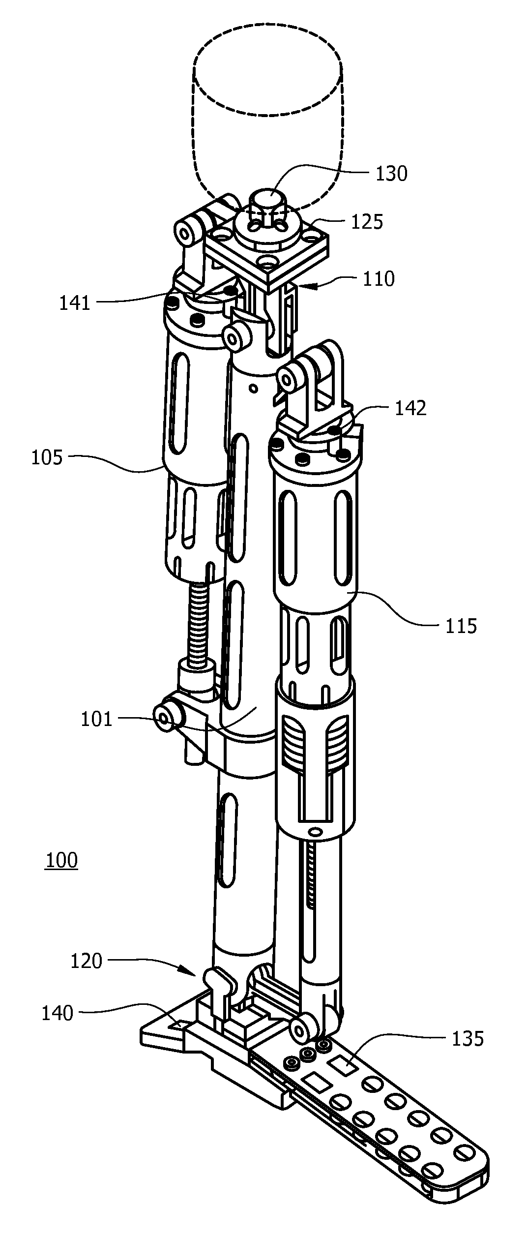
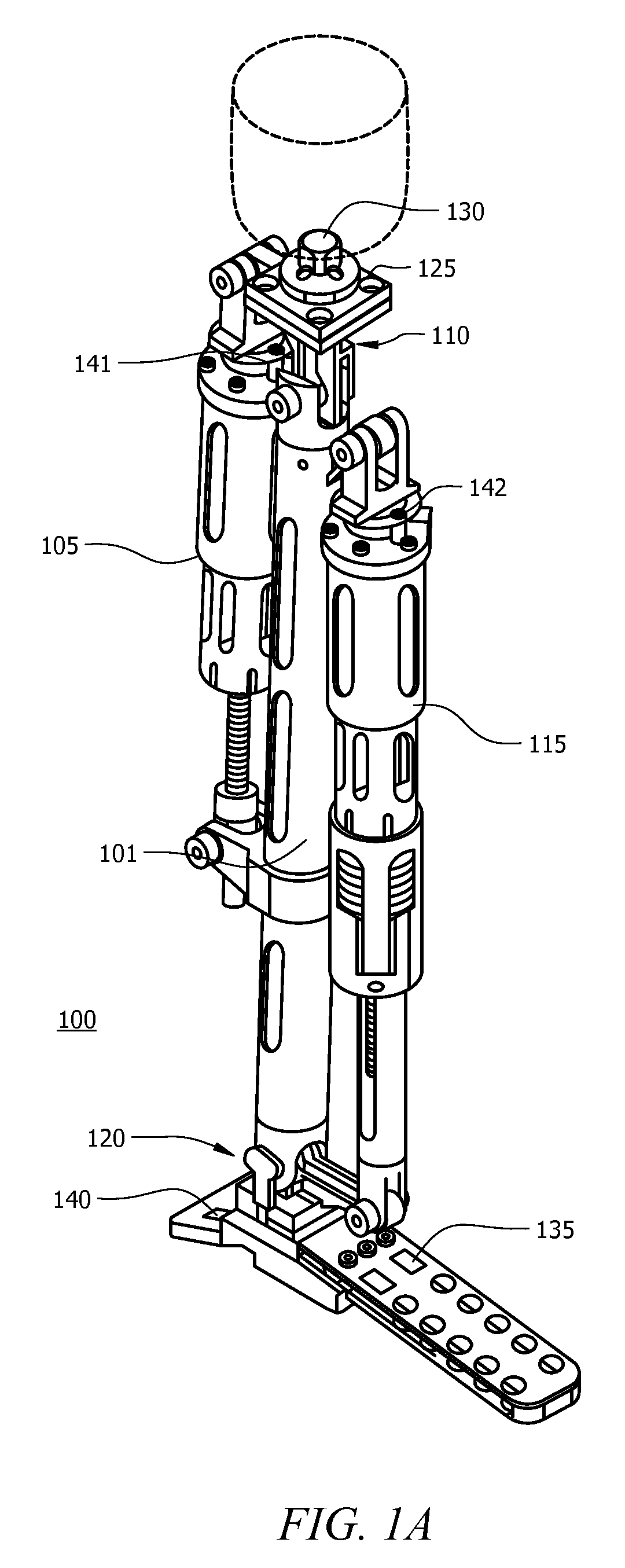
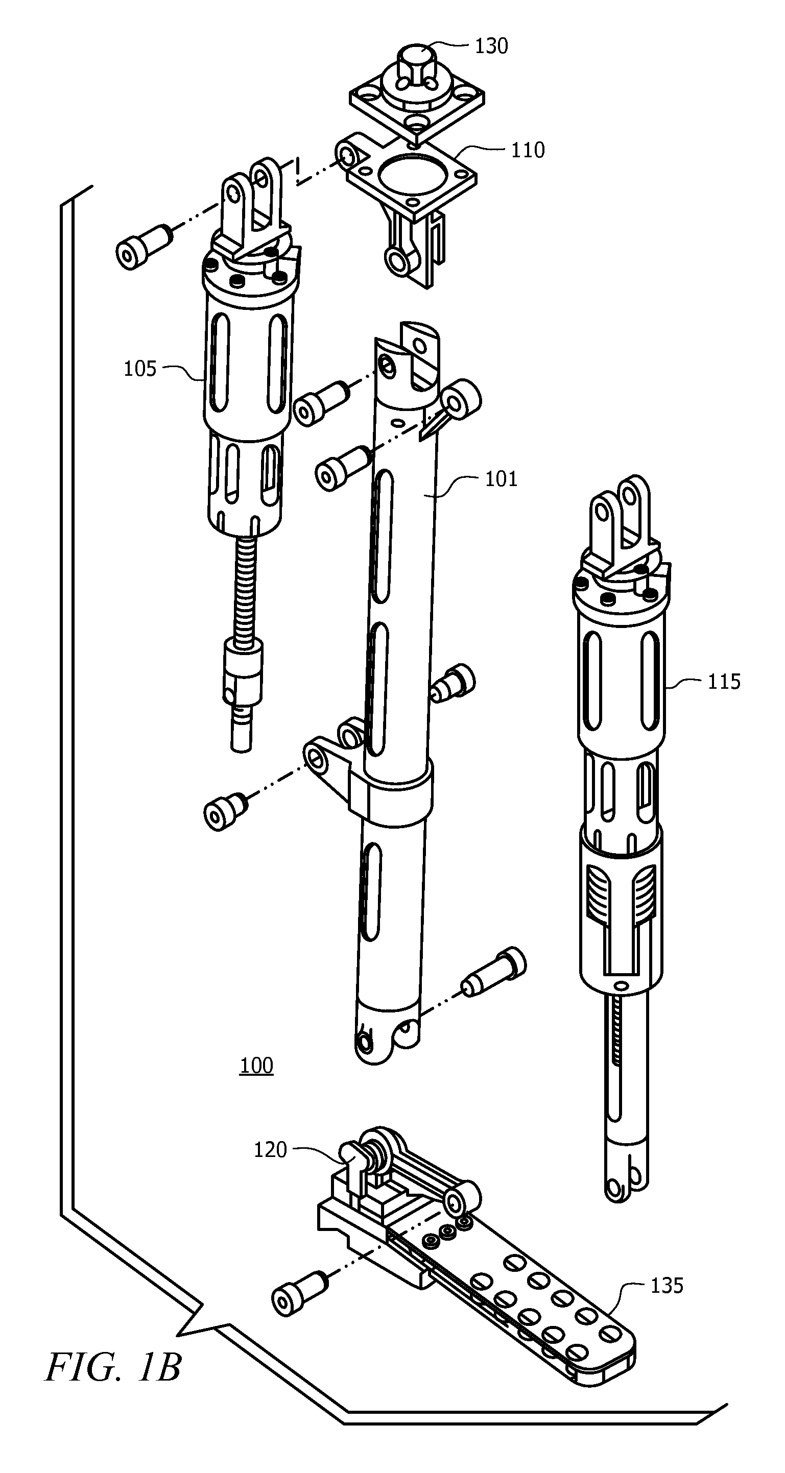
[0038]The invention is described with reference to the attached figures, wherein like reference numerals are used throughout the figures to designate similar or equivalent elements. The figures are not drawn to scale and they are provided merely to illustrate the instant invention. Several aspects of the invention are described below with reference to example applications for illustration. It should be understood that numerous specific details, relationships, and methods are set forth to provide a full understanding of the invention. One having ordinary skill in the relevant art, however, will readily recognize that the invention can be practiced without one or more of the specific details or with other methods. In other instances, well-known structures or operations are not shown in detail to avoid obscuring the invention. The invention is not limited by the illustrated ordering of acts or events, as some acts may occur in different orders and / or concurrently with other acts or eve...


PUM


Abstract

A powered leg prosthesis includes powered knee joint comprising a knee joint and a knee motor unit for delivering power to the knee joint. The prosthesis also includes a prosthetic lower leg having a socket interface coupled to the knee joint and a powered ankle joint coupled to the lower leg opposite the knee joint comprising an ankle joint and an ankle motor unit to deliver power to the ankle joint. The prosthesis further includes a prosthetic foot coupled to the ankle joint, at least one sensor for measuring a real-time input, and at least one controller for controlling movement of the prosthesis based on the real-time input.

Description

CROSS REFERENCE TO RELATED APPLICATIONS[0001]This application claims the benefit of Provisional Application Ser. No. 61 / 046,684 entitled “POWERED LEG PROSTHESIS AND CONTROL METHODOLOGIES FOR OBTAINING NEAR NORMAL GAIT”, filed Apr. 21, 2008, which is herein incorporated by reference in its entirety.FEDERAL RIGHTS STATEMENT[0002]The U.S. Government may have certain rights to the invention based on National Institutes of Health Grant R01EB005684-01.FIELD OF THE INVENTION[0003]The invention relates to a powered leg prosthesis and control methodologies for controlling the prosthesis.BACKGROUND[0004]Leg prostheses can provide an artificial ankle, and artificial knee, or both an artificial ankle and an artificial knee. A transfemoral prosthesis is a prosthesis designed for above the knee amputees. Transfemoral prostheses are generally more complicated than transtibial prostheses, as they must include a knee joint.[0005]Nearly all current commercial transfemoral comprising prostheses are en...

Claims


Application Information

Patent Timeline
Patent Type & Authority Applications(United States)
IPC IPC(8): A61F2/64
CPCA61F2/60A61F2/66A61F2/68A61F2002/30359A61F2002/5073A61F2002/6642A61F2002/665A61F2002/6657A61F2002/6836A61F2002/701A61F2002/704A61F2002/705A61F2002/7625A61F2002/7635A61F2002/764A61F2002/7645A61F2002/768A61F2220/0033A61F2/64A61F2/72A61F2/6607
Inventor GOLDFARB, MICHAELVAROL, HUSEYIN ATAKANSUP, IV, FRANK CHARLESMITCHELL, JASONWITHROW, THOMAS J.
Owner VANDERBILT UNIV
Why Eureka
Try Eureka