Arrangement for operating a hydraulic device

a hydraulic device and arrangement technology, applied in the direction of fluid couplings, positive displacement liquid engines, couplings, etc., can solve the problems of over-extended torque required the torque required for supplying sufficient pressure from the first pump unit may be in excess of the maximum available torque from the prime mover, so as to achieve more energy efficiency

Inactive Publication Date: 2009-10-29
PARKER INTANGIBLES LLC
View PDF58 Cites 22 Cited by
  • Summary
  • Abstract
  • Description
  • Claims
  • Application Information

AI Technical Summary

Benefits of technology

[0023]This torque equalizing device will make it possible to use of more energy efficient machines by allowing downsizing of essential components, such as prime movers and transmissions in fluid operated systems, in particular in fluid operated implements and systems for vehicles.

Problems solved by technology

During periods of low demand, the available torque from the prime mover exceeds the torque required by the first pump unit to supply the fluid implement with sufficient fluid pressure.
When the fluid implement is subjected to sudden peak loads or higher than normal loads, the torque required for supplying sufficient pressure from the first pump unit may be in excess of the maximum available torque from the prime mover.

Method used


Image

  • Arrangement for operating a hydraulic device
  • Arrangement for operating a hydraulic device
  • Arrangement for operating a hydraulic device

Examples


first embodiment

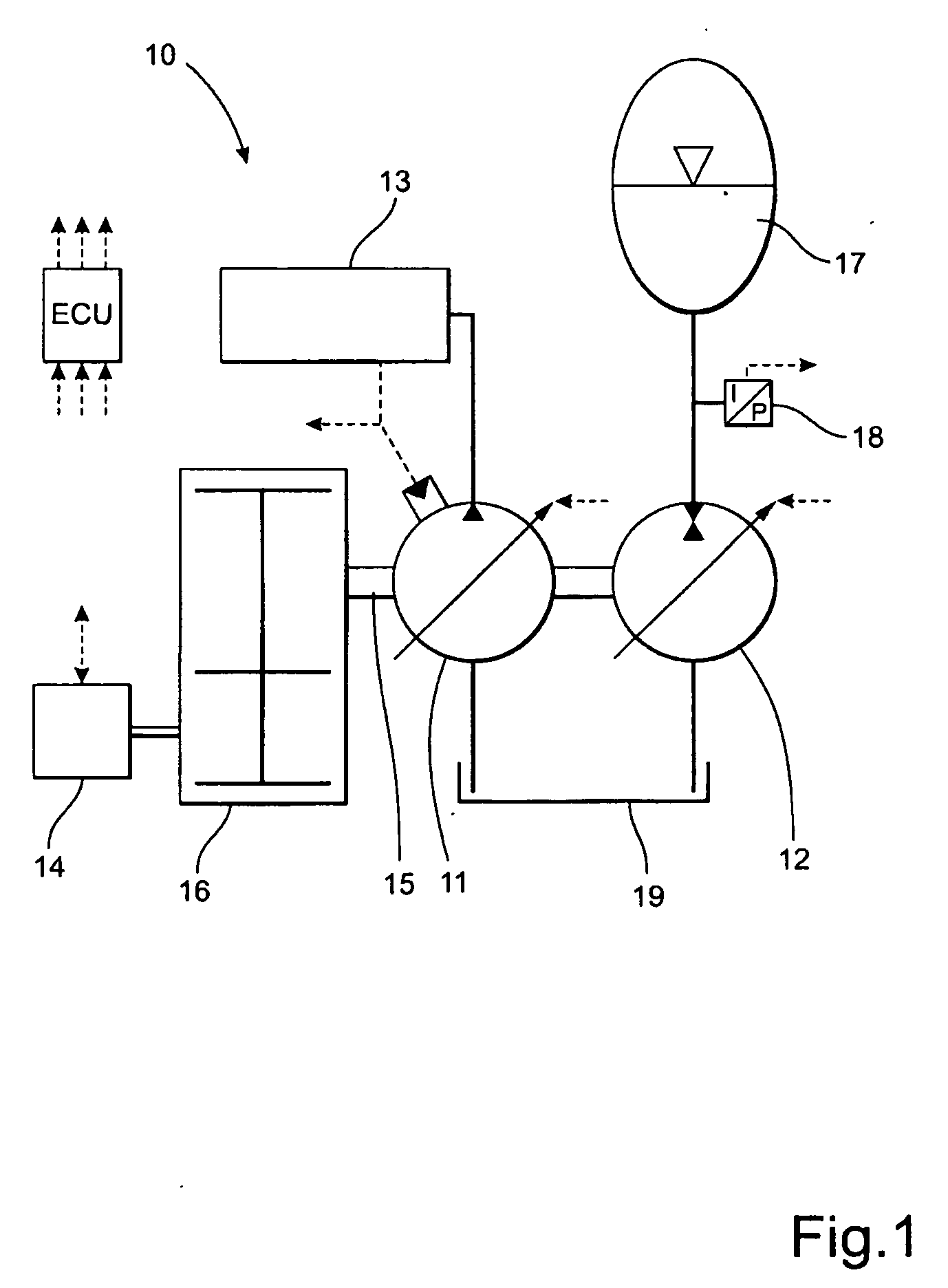
[0028]FIG. 1 shows a schematic illustration of a hydraulic system according to the invention. The figure shows a hydraulic system 10 comprising a controllable first pump unit in the form of a variable displacement pump 11 for supplying hydraulic pressure to a hydraulically driven device in the form of a hydraulic cylinder 13. The controllable first pump unit will hereafter be referred to as the first pump 11. A prime mover in the form of an engine 14 is arranged to supply a driving torque to a drive shaft 15 for the first pump 11 via a transmission in the form of a hydrodynamic gearbox 16. The hydraulic system 10 further comprises a controllable second pump unit in the form of a variable displacement pump 12 connected to a hydraulic accumulator 17. The controllable second pump unit will hereafter be referred to as the second pump 12. The engine 14 is further arranged to supply a driving torque to the second pump 12. The second pump 12 is arranged to be driven as a pump and accumulat...

second embodiment

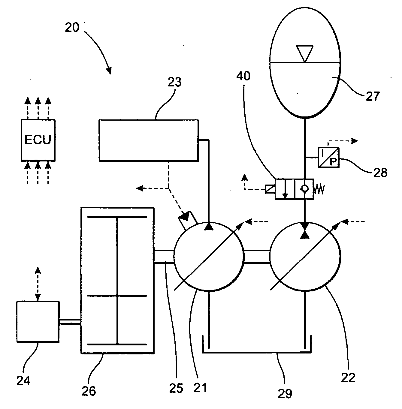
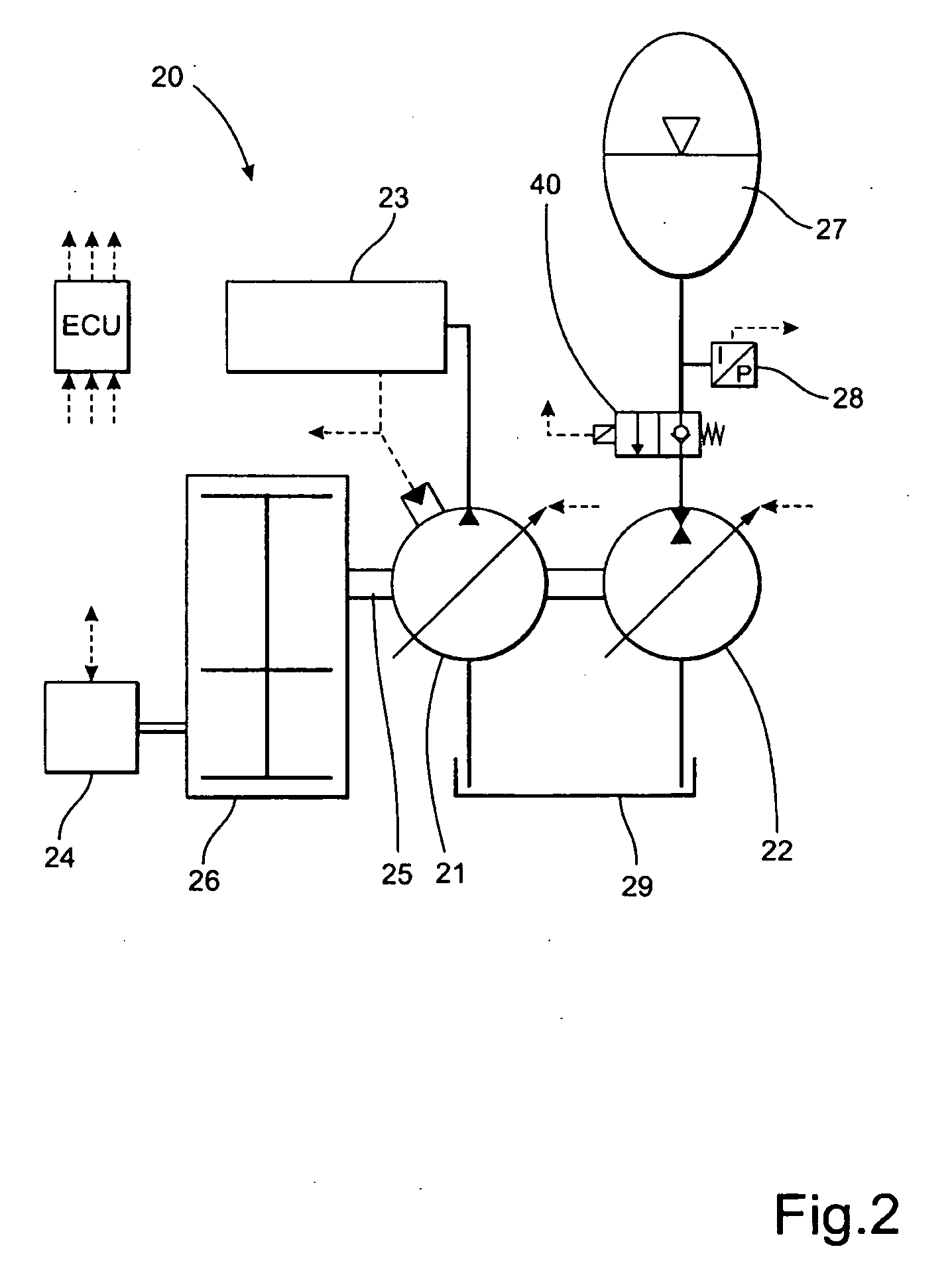
[0031]FIG. 2 shows a schematic illustration of a hydraulic system according to the invention. As in FIG. 1, FIG. 2 shows a hydraulic system 20 comprising a controllable first pump unit in the form of a variable displacement pump 21 for supplying hydraulic pressure to a hydraulically driven device in the form of a hydraulic cylinder 23. The controllable first pump unit will hereafter be referred to as the first pump 21. A prime mover in the form of an engine 24 is arranged to supply a driving torque to a drive shaft 25 for the first pump 21 via a transmission in the form of a hydrodynamic gearbox 26. The hydraulic system 20 further comprises a controllable second pump unit in the form of a variable displacement pump 22 connected to a hydraulic accumulator 27. The controllable second pump unit will hereafter be referred to as the second pump 22. The engine 24 is further arranged to supply a driving torque to the second pump 22. The second pump 22 is arranged to be driven as a pump and...

third embodiment

[0034]FIG. 3 shows a schematic illustration of a hydraulic system according to the invention. The figure shows a hydraulic system 30 comprising a controllable first pump unit 31 in the form of a first variable displacement device for supplying hydraulic pressure to a hydraulically driven device in the form of a hydraulic cylinder 33. The controllable first pump unit will hereafter be referred to as the first pump 31. A prime mover in the form of an engine 34 is arranged to supply a driving torque to a drive shaft 35 for the first pump 31 via a transmission in the form of a hydrodynamic gearbox 36. The hydraulic system 30 further comprises a controllable second pump unit in the form of a variable displacement pump 32 connected to a hydraulic accumulator 37. The controllable second pump unit will hereafter be referred to as the second pump 32. The engine 34 is further arranged to supply a driving torque to the second pump 32. The second pump 32 is arranged to be driven as a pump and a...


PUM


Abstract

A fluid system includes a controllable first pump unit for supplying fluid pressure to at least one implement; a prime mover arranged to supply a driving torque to the first pump The first pump unit is arranged to supply fluid pressure to the implement. The fluid system further includes a controllable second pump unit connected to a fluid accumulator. The prime mover is arranged to supply a driving torque to the second pump unit in order to accumulate fluid pressure in the accumulator during periods of low demand. Fluid pressure from the accumulator is arranged to drive the second pump unit to assist the prime mover during periods of high demand in order to supply an additional driving torque in excess of the available driving torque from the prime mover.

Description

CROSS-REFERENCE TO RELATED CASE[0001]The present application claims the benefit of the filing date of European Patent Application No. 08155350.5, filed Apr. 29, 2008, the disclosure of which is expressly incorporated herein by reference.TECHNICAL FIELD[0002]The invention relates to a fluid system comprising a first pump unit for supplying fluid pressure to at least one implement, where a prime mover is arranged to supply a driving torque to the first pump unit. The prime mover is also arranged to supply a driving torque to a second pump unit in order to accumulate fluid pressure in an accumulator during periods of low demand, in order to assist the prime mover during periods of high demand.BACKGROUND ART[0003]Fluid systems for wheel loaders, forklift trucks, container handling machines and other machines or equipment are equipped with a prime mover for driving a fluid pump for instance via a gearbox. A problem with such a system is that the peak pressure is limited to the maximum fl...

Claims


Application Information

Patent Timeline
Patent Type & Authority Applications(United States)
IPC IPC(8): F15B1/027F16D31/02F04B41/06
CPCF15B21/14F15B1/024
Inventor PERSSON, BENGT GORANNILSSON, PETER
Owner PARKER INTANGIBLES LLC
Why Eureka
Try Eureka