Real time lead-line characterization for mfc flow verification

a real-time lead-line characterization and flow verification technology, applied in the direction of water supply installation, operating means/releasing devices of valves, instruments, etc., can solve the problems of poor emission control, processing defects, and the inability to accurately determine the gas flow of the m

Active Publication Date: 2009-10-29
APPLIED MATERIALS INC
View PDF14 Cites 44 Cited by
  • Summary
  • Abstract
  • Description
  • Claims
  • Application Information

AI Technical Summary

Benefits of technology

[0015]In yet another embodiment, a method for controlling gas flow in a gas delivery system is provided. The gas delivery system comprises a gas source, a mass flow controller coupled with the gas source, a mass flow verifier, a lead-line coupling the mass flow controller with the mass flow verifier, and a temperature and pressure transducer coupled with the lead-line. Furthermore, the das delivery system is connected to a controller using analog and di

Problems solved by technology

However, the accuracy of MFC's may be affected by a plurality of factors that contribute to an uncertainty of the actual gas flow.
Deviation from the gas flow set point due to MFC inaccuracy may contribute to processing defects, poor emission control and inefficien

Method used


Image

  • Real time lead-line characterization for mfc flow verification
  • Real time lead-line characterization for mfc flow verification
  • Real time lead-line characterization for mfc flow verification

Examples


Embodiment Construction

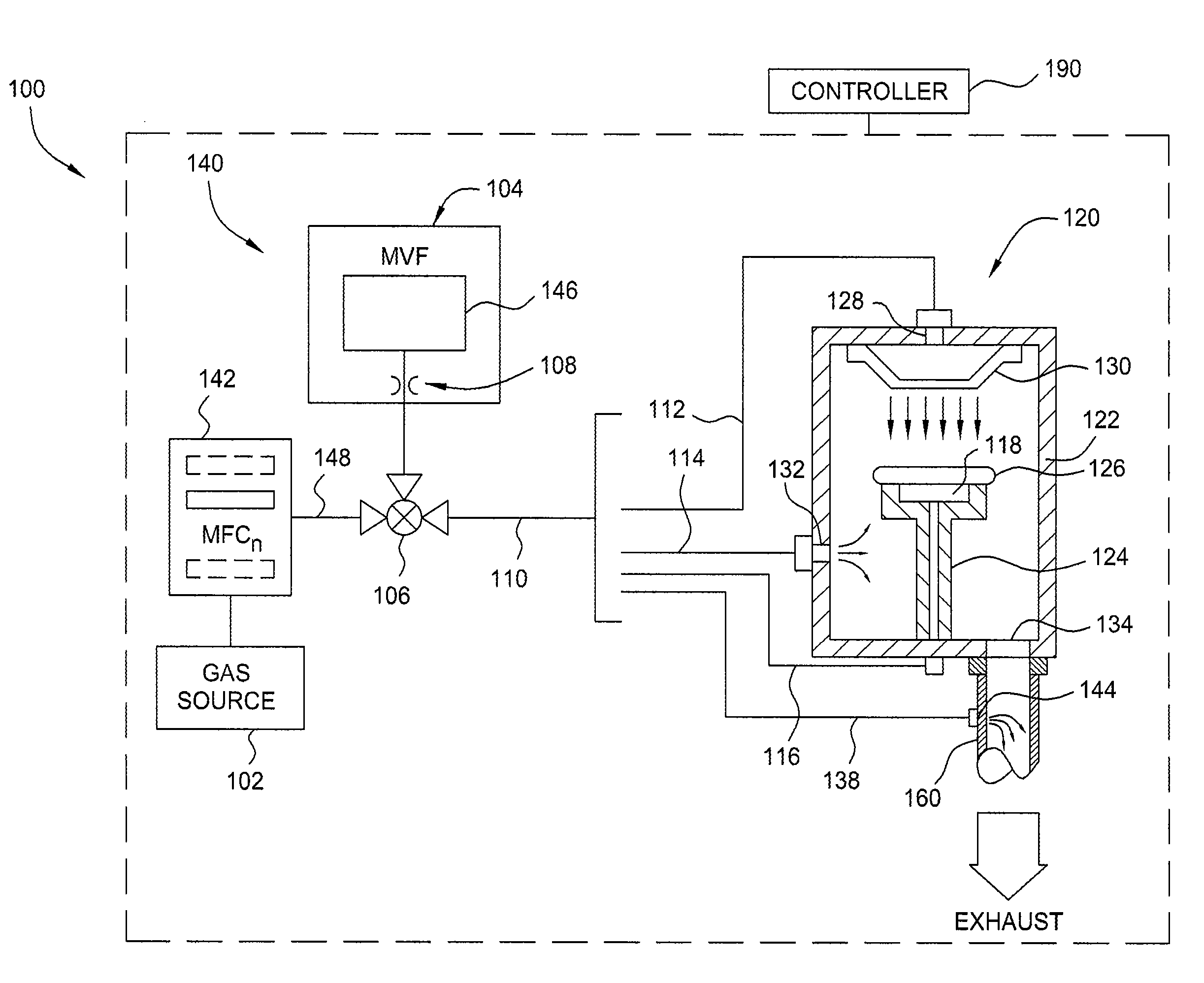
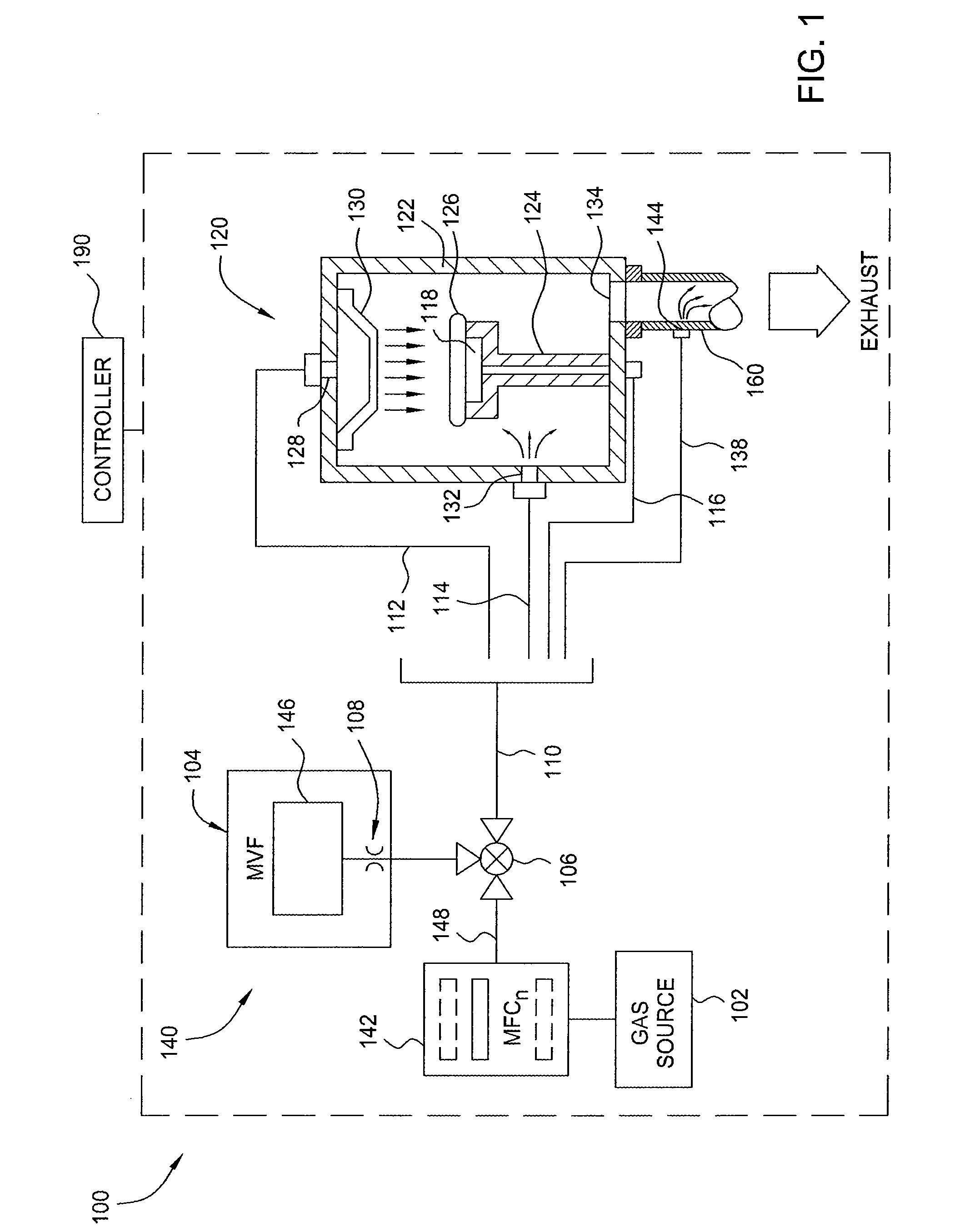
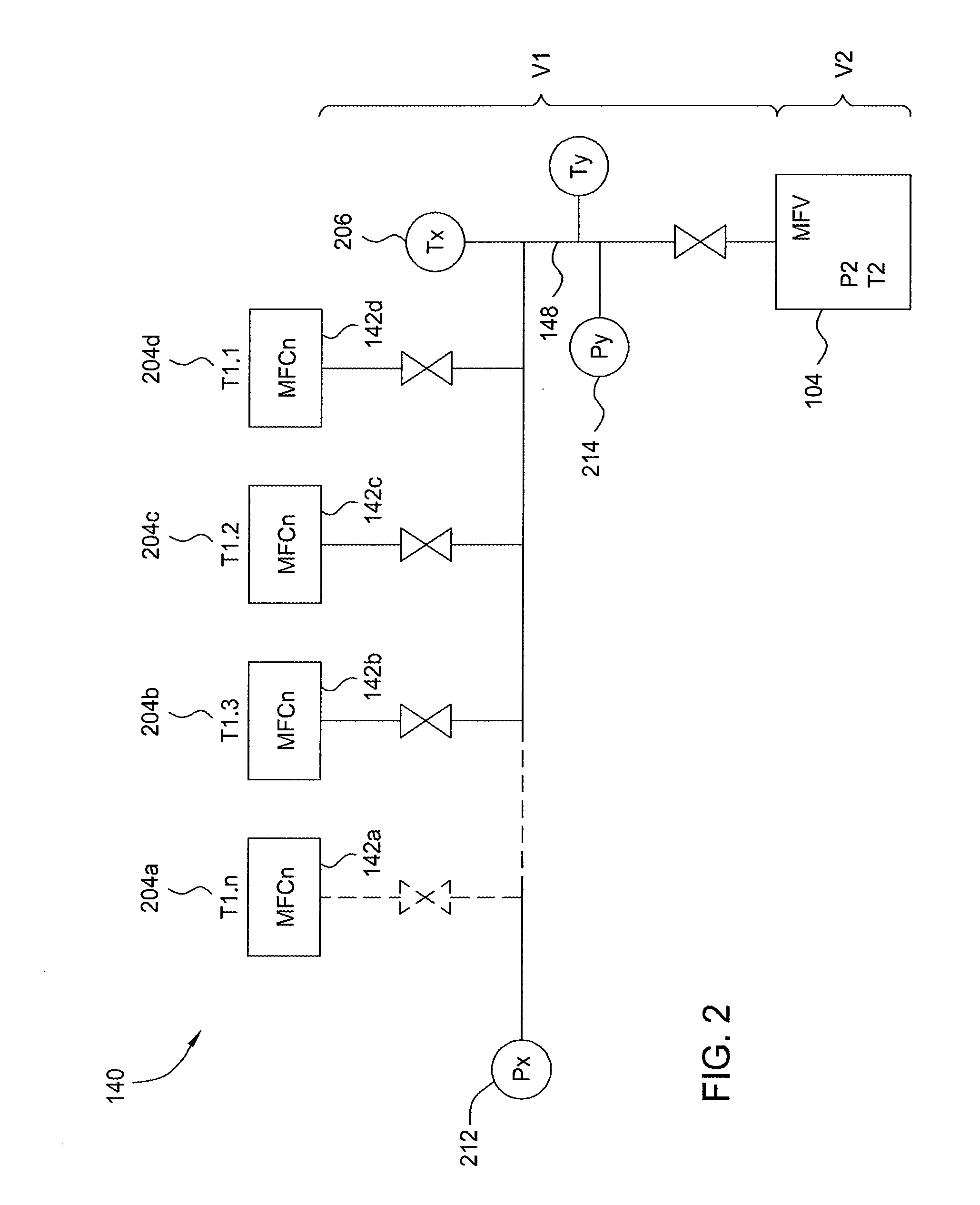
[0023]A Mass Flow Verifier (MFV) validates the accuracy of a Mass Flow Controller (MFC) by measuring the rate of change of pressure in a fixed volume. The MFV utilizes a controlled volume with attached pressure and temperature measurement devices to determine the pressure change during a Rate of Rise (RoR) test. This change in pressure is used to determine flow into the controlled volume of the MFV. The average mass flow of gas into the controlled volume during a time interval delta t (Δt) is calculated simply by the difference of mass in the volume at time (t)=1 minus the mass at (t)=0 divided by delta t(Δt).

Mass Flow=(mT(t=1)−mT(t=0)) / Δt mT=total mass   (0)

[0024]The connecting line or lead-line between the MFC and the MFV adds an error to the controlled volume of the MFV. Since the lead-line can have a considerable volume, this additional volume must be taken into account. In order to perform a RoR test with attached lead-line, the mass of the gas in the lead-line must be added to...


PUM


Abstract

A method and apparatus that solve the problem of accurate measurement of gas flow so that the delivery of gases in semiconductor processing may be performed with greater confidence and accuracy by performing real-time characterization of a lead-line for mass flow controller (MFC) flow verification are provided. In one embodiment a mass flow verifier (MFV) provides rate of rise information to a controller via a digital interface without correcting for lead-line influences. After receiving the rate of rise data from the tool host computer computes a gas mass correction factor in real-time based on at least one of the following: MFC temperature sensor data, lead-line temperature sensor data, lead-line pressure transducer data, and lead-line volume. The rate of rise data and gas mass correction factor are used to compute accurate mass flow. The accurate mass flow information may be used to calibrate the MFC.

Description

CROSS-REFERENCE TO RELATED APPLICATIONS[0001]This application claims benefit of U.S. Provisional Patent Application Ser. No. 61 / 047,970, filed Apr. 25, 2008, which is hereby incorporated by reference.BACKGROUND OF THE INVENTION[0002]1. Field of the Invention[0003]Embodiments described herein generally relate to a method and apparatus for measuring gas flow. More specifically, embodiments of the invention generally relate to a method and apparatus for measuring gas flows that are provided to a semiconductor processing chamber and related utilities.[0004]2. Description of the Related Art[0005]Accurate control of gas flows is an important process control attribute critical to many microelectronic device fabrication processes. Precise control of process gas flows into the processing chamber is required in order to obtain desired processing results, particularly as critical dimensions and film thicknesses shrink.[0006]Conventional gas delivery systems used with semiconductor processing c...

Claims


Application Information

Patent Timeline
IPC IPC(8): G01F25/00
CPCG01F25/0038G01F25/003Y10T137/7759Y10T137/0324G01F25/17G01F25/13
Inventor GREGOR, MARIUSCHLANE, JOHN W.
Owner APPLIED MATERIALS INC
Why Eureka
Try Eureka