Thermal type gas flow measuring instrument

a technology of gas flow and measuring instrument, which is applied in the direction of instruments, electric control, machines/engines, etc., to achieve the effect of accurately correcting changes and high-precision gas flow

Inactive Publication Date: 2005-06-23
HITACHI LTD +1
View PDF6 Cites 8 Cited by
  • Summary
  • Abstract
  • Description
  • Claims
  • Application Information

AI Technical Summary

Benefits of technology

[0024] Thus, in accordance with the invention, a highly accurate gas flow measuring apparatus can be provided that is capable of accurately correcting changes in the radiation heat characteristics of the heating resistor due to contamination.

Problems solved by technology

As a result, most of the dust components in the intake air are adsorbed on the air cleaner filter and does not therefore reach the heat wire portion of the instrument.

Method used


Image

  • Thermal type gas flow measuring instrument
  • Thermal type gas flow measuring instrument
  • Thermal type gas flow measuring instrument

Examples


Embodiment Construction

[0031] The invention is described in detail hereafter by way of a preferred embodiment thereof, with reference made to the attached drawings.

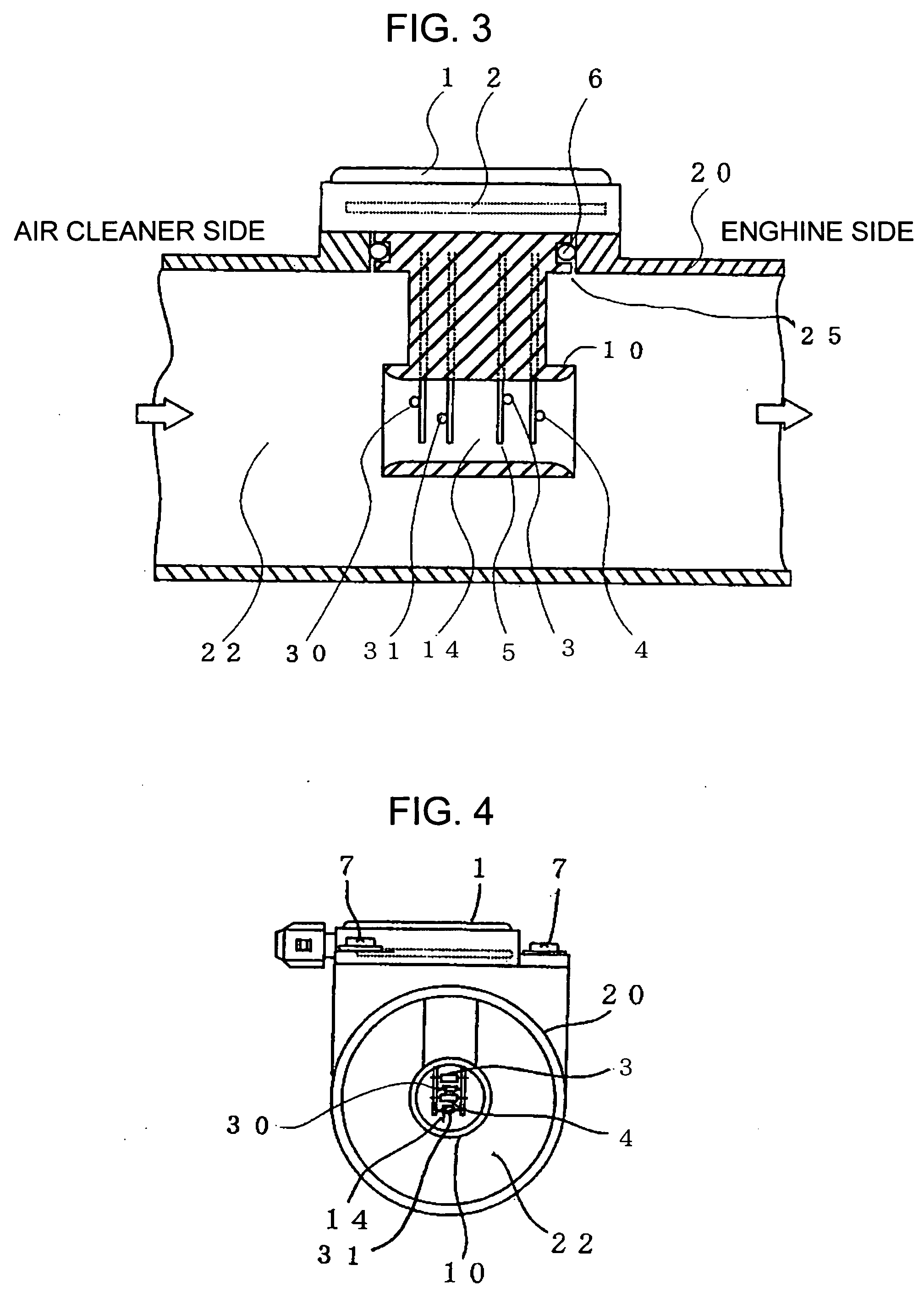
[0032] The embodiment as described below is an example in which the invention is applied to a thermal type air flow measuring instrument used for controlling the operation of an internal combustion engine.

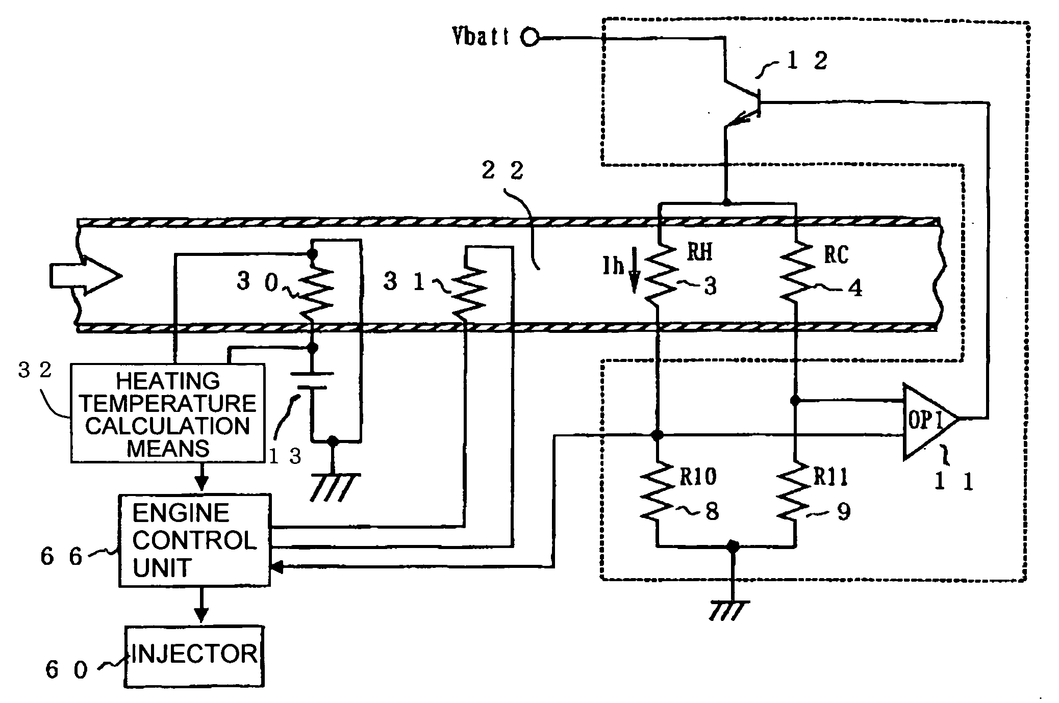
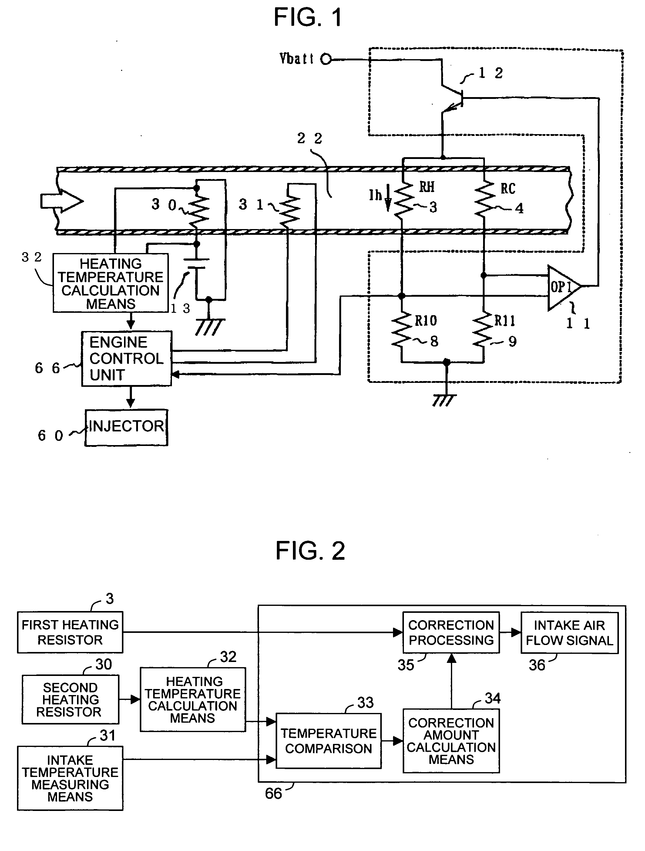
[0033] The operation principle of the thermal type air flow measuring instrument of the invention is described with reference to FIG. 1 showing a schematic circuit diagram of the instrument according to the embodiment.

[0034] A drive circuit of the thermal type air flow measuring instrument is mainly made up of a bridge circuit and a feedback circuit. The bridge circuit includes a first heating resistor 3 for measuring intake air flow, a temperature sensing resistor 4 for compensating the intake air temperature, a resistor 8 connected in series with the temperature sensing resistor 4, and a resistor 9 connected in series with the heating res...


PUM


Abstract

A thermal type gas flow measuring instrument measures gas flow with high precision by accurately correcting changes in radiation heat characteristics of a heating resistor due to contamination. The instrument comprises a second heating resistor 30 whose resistance value, which changes if contaminated, is calculated by measuring the terminal voltage thereof by calculating means 32, and the calculated value is compared with a temperature detected by a temperature detecting element 31. Based on the result of comparison, the level of contamination of the second heating resistor 30 is determined. The second heating resistor 30 and the first heating resistor 3 are disposed in similar environments such that their levels of contamination can be considered equal. Based on the level of contamination calculated from the result of comparison, a correction value is calculated and the output of the first heating resistor 3 is corrected in accordance with the correction value.

Description

BACKGROUND OF THE INVENTION [0001] 1. Field of the Invention [0002] The invention relates to a thermal type gas flow measuring instrument or measuring gas flow, such as air flow. [0003] 2. Description of Related Art [0004] As an example of the gas flow type measuring instrument, a thermal type air flow measuring instrument is known for measuring the intake air flow in automobile internal combustion engines. [0005] This thermal type air flow measuring instrument takes advantage of the fact that the amount of heat dissipated from a heating resistor increases at a steady rate relative to the intake air flow. Because of its capability to directly measure the mass flow, it is widely utilized as a flow measuring device for automobile fuel control purposes. [0006] As a technology for improving the accuracy of flow measurement in the above-mentioned thermal type air flow measuring instrument, Patent Document 1 discloses an invention entitled “Method for controlling an internal combustion en...

Claims


Application Information

Patent Timeline
Patent Type & Authority Applications(United States)
IPC IPC(8): F02D41/18G01F1/696G01F1/698
CPCF02D41/187G01F1/6983G01F1/6965
Inventor KOBAYASHI, CHIHIROIGARASHI, SHINYA
Owner HITACHI LTD
Why Eureka
Try Eureka