Instruction inputting device

Inactive Publication Date: 2009-10-29
SMK CORP
View PDF9 Cites 12 Cited by
  • Summary
  • Abstract
  • Description
  • Claims
  • Application Information

AI Technical Summary

Benefits of technology

[0034]It is also possible to form a pair of adjacent branch patterns, around the Z axis, without mutually overlapping these patterns, so as to form a large surface area, without wasting the limited spherical crown unit surface, and thus possible to detect with greater precision the increase in floating capacitance due to the proximity of the object to be detected.
[0035]Further, it is possible to detect an input operation on to the apex from the increase in all of the floating capacitances of the X+ electrode and X− electrode and the floating capacitances of the Y+ electrode and

Problems solved by technology

The trackball device, wherein a ball is rotated with a finger and the direction of rotation of the ball serves as the input operation direction and the direction of rotation, is known as an input device for movement operations for cursors or characters that are displayed on a display of a computer or a game machine, or the like; however, the ball requires an installation space commensurate with the diameter of the ball, becoming a hindrance to miniaturization of computers and game machines.
Furthermore, because the position of the input operation is detected by reading the change in voltage fo

Method used


Image

  • Instruction inputting device
  • Instruction inputting device
  • Instruction inputting device

Examples


Embodiment Construction

[0048]A listing of some of the reference numerals and letters that are used in the drawings, together with descriptions of the corresponding elements, is provided below:

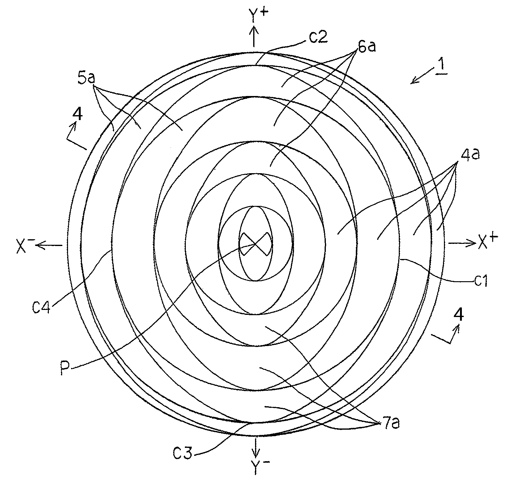
[0049]1. Instruction Inputting Device

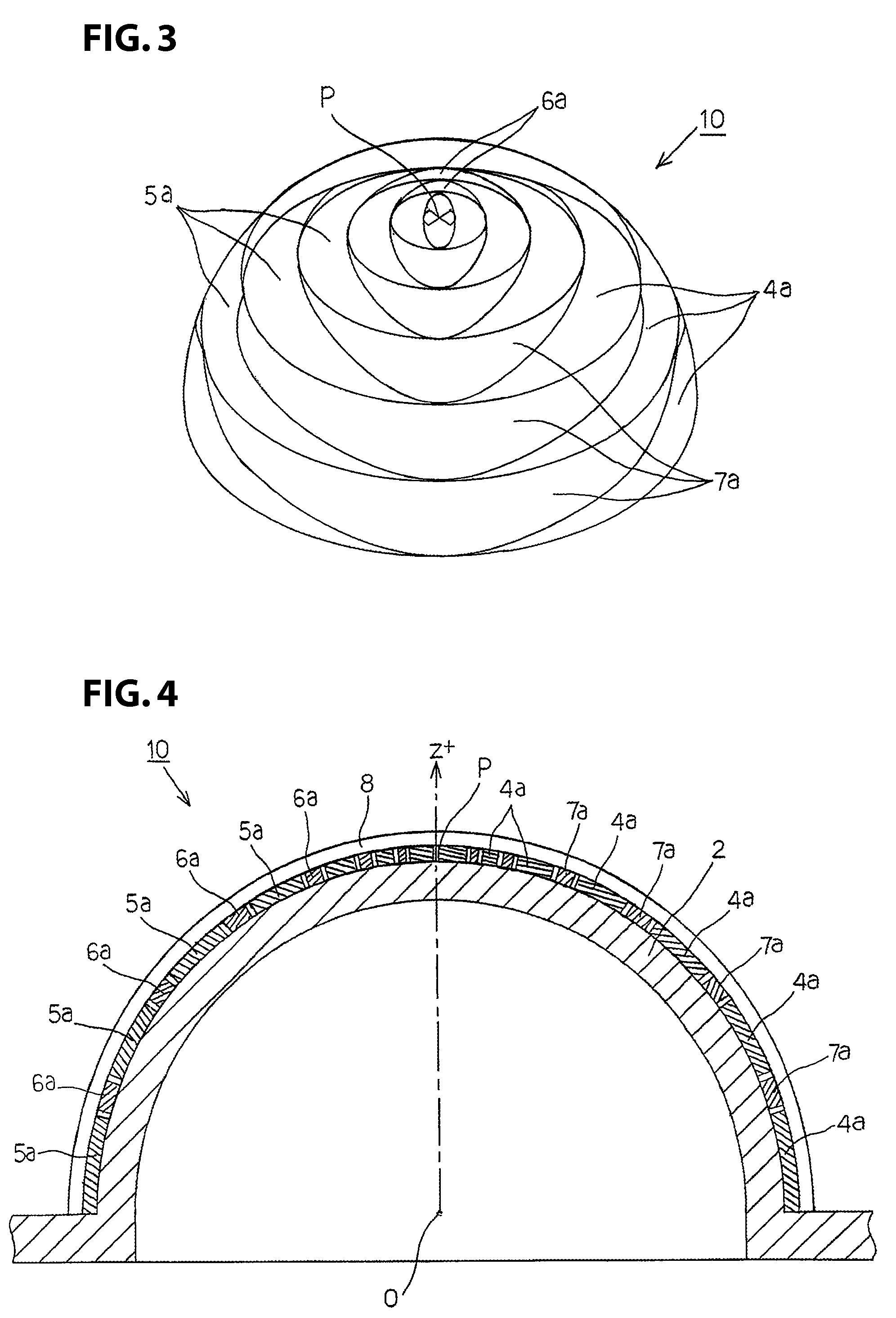
[0050]2. Spherical Crown Unit

[0051]4. X+ Electrode

[0052]4a. X+ Branch Pattern

[0053]5. X− Electrode

[0054]5a. X− Branch Pattern

[0055]6. Y+ Electrode

[0056]6a. Y+ Branch Pattern

[0057]7. Y− Electrode

[0058]7a. Y− Branch Pattern

[0059]21. Floating Capacitance Detecting Means (C / E Converting Circuit)

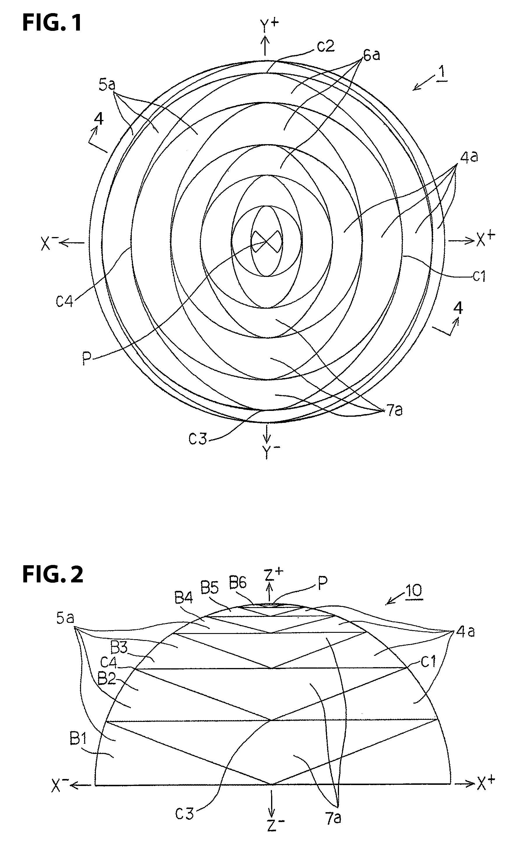
[0060]B. Spherical Zone

[0061]P. Apex

[0062]An exemplary instruction inputting device 1 according to the present invention will be explained below with reference to FIG. 1 through FIG. 7.

[0063]The instruction inputting device 1 includes an input operating portion 10 for performing the input operation through bringing a finger, which is the object to be detected, into proximity, and an input operation detecting circuit portion 20 for detecting input operations in the planar direction and in the ro...


PUM


Abstract

An instruction inputting device detects input operations in the XY plane and in a rotational direction on a hemispherical input operation surface. Four detection electrodes insulated from each other are formed at 90° intervals around the Z axis of the hemisphere, on the surface of a spherical crown-shaped insulator. Surface areas of each of the detection electrodes decrease moving toward an apex P on the Z axis and moving in a circumferential direction away from the positions at which the 90° intervals are formed. As a result, the surface areas of the detection electrodes facing an object to be detected for causing the input operation differ depending on the positioning of the object, thereby causing differences in the floating capacitances of the detection electrodes which are sensed by a circuit portion of the device.

Description

CROSS REFERENCE TO RELATED APPLICATION[0001]This application claims the benefit under 35 U.S.C. §119 of Japanese Patent Application No. 2008-115241, filed on Apr. 25, 2008, which is hereby incorporated by reference herein in its entirety.FIELD OF THE INVENTION[0002]The present invention relates to instruction inputting devices of a static capacitance type for detecting, by a change in floating capacitance of an electrode that is formed on the input operation surface, an input operation of an object to be detected, such as a finger on a hemispherical input operation surface, and more specifically, relates to an instruction inputting device for detecting an input operation of an XY direction and a rotational direction into a hemispherical input operation surface with few detection electrodes.BACKGROUND OF THE INVENTION[0003]The trackball device, wherein a ball is rotated with a finger and the direction of rotation of the ball serves as the input operation direction and the direction o...

Claims


Application Information

Patent Timeline
IPC IPC(8): G06F3/041
CPCG06F3/044H03K2217/96072H03K17/9622G06F3/0446
Inventor YOSHIKAWA, OSAMU
Owner SMK CORP
Why Eureka
Try Eureka