Silencer

a technology of silencer and cylinder, which is applied in the direction of positive displacement liquid engine, transducer diaphragm, instruments, etc., can solve the problems of clogging, affecting the operation of the fluid pressure device connected to the silencer, and reducing the temperature inside the silencer, so as to prevent condensation, reduce exhaust noise, and suppress the occurrence of clogging

Active Publication Date: 2009-10-29
SMC CORP
View PDF27 Cites 17 Cited by
  • Summary
  • Abstract
  • Description
  • Claims
  • Application Information

AI Technical Summary

Benefits of technology

[0006]A principal object of the present invention is to provide a silencer, which is capable of suppressing generation of clogging, while causing a reduction in exhaust noises, along with preventing the occurrence of condensation when the pressure fluid is exhausted.

Problems solved by technology

However, in the aforementioned silencer, when the pressure fluid is caused to flow toward the silencer from the fluid pressure device, the pressure drops precipitously in the vicinity of a connection part between the silencer and the fluid pressure device where the pressure fluid is released to atmosphere, and further, the temperature inside the silencer drops as a result of adiabatic expansion of the pressure fluid.
Accordingly, owing to the reduction in temperature, moisture that is contained within the pressure fluid condenses in the vicinity of the connection part, and at the reduced temperature, such condensation becomes frozen at the interior of the silencer, resulting in a concern that operations of the fluid pressure device connected to the silencer may be adversely affected.
Further, in the case that the filtering capability of the filter is raised, with the aim of further reducing pressure fluid exhaust noises, clogging can easily be generated as a result of dust contained within the pressure fluid, with the problem that a desired noise reduction effect may not be obtainable.

Method used


Image

  • Silencer
  • Silencer
  • Silencer

Examples


first embodiment

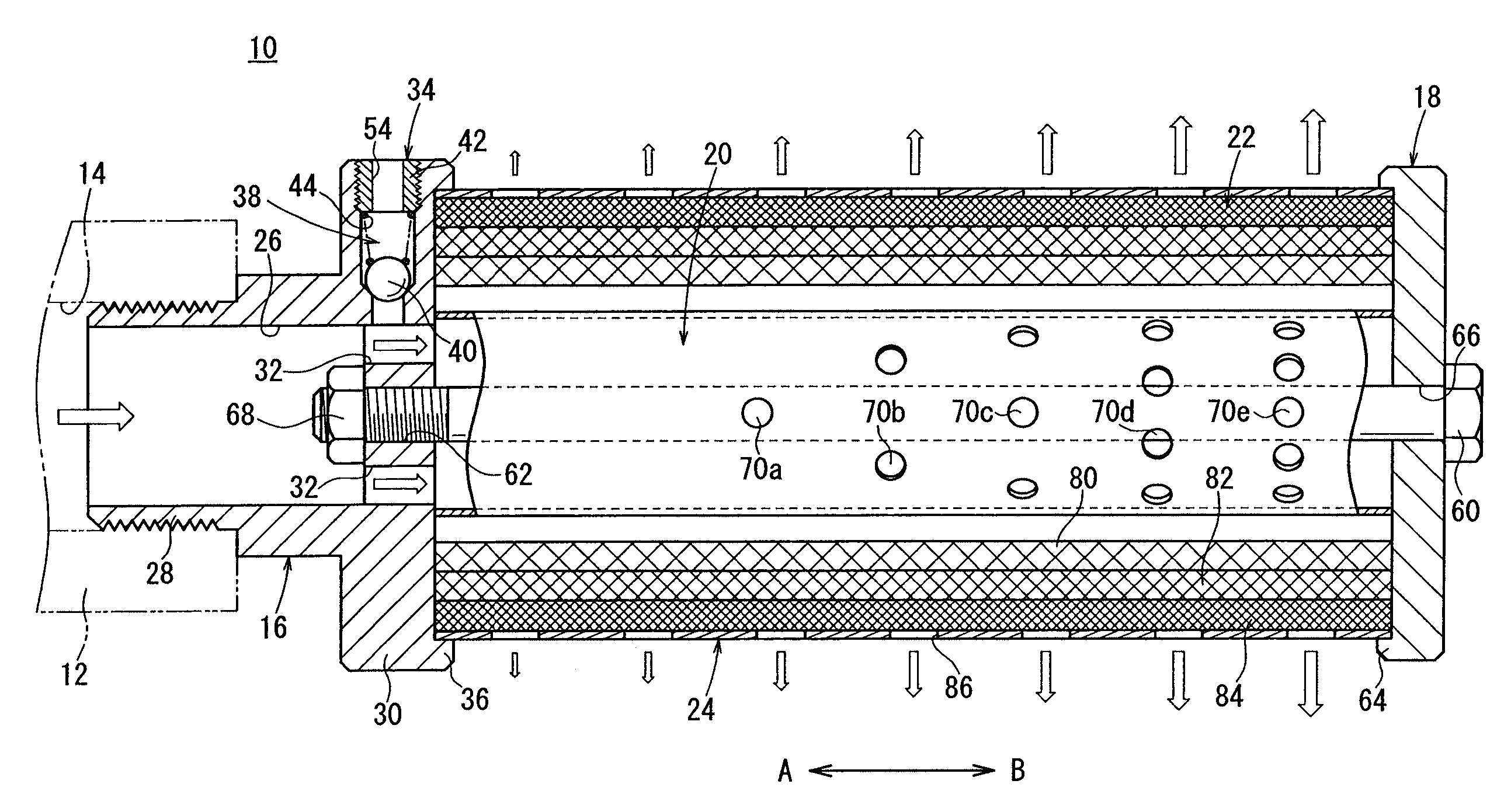
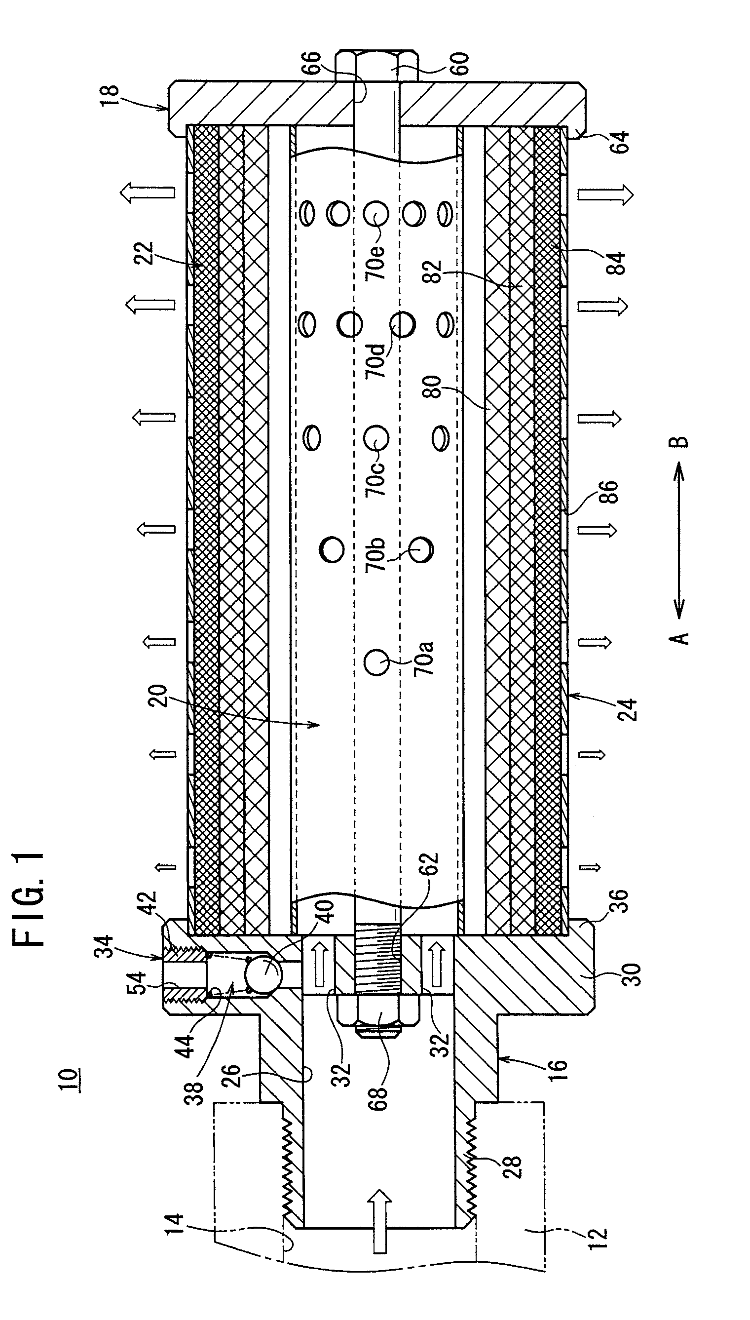
[0022]In FIG. 1, reference numeral 10 indicates a silencer according to the present invention.

[0023]The silencer 10 includes a body (main body portion) 16 connected to an exhaust port 14 of a fluid pressure device 12 (for example a solenoid valve), a retaining member 18 disposed coaxially with and separated a predetermined interval away from the body 16, a cylindrical member (cylindrical body) 20 sandwiched between the body 16 and the retaining member 18, a sound absorber 22 disposed on an outer circumferential side of the cylindrical member 20 for reducing exhaust noises of a pressure fluid that is discharged from the fluid pressure device 12, and a cylindrically shaped cover member 24 disposed on the outer circumference of the sound absorber 22.

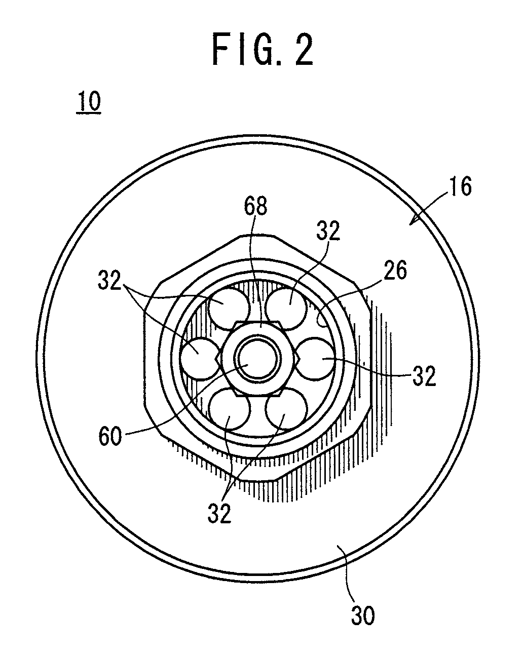
[0024]The body 16 is equipped with a connecting portion 28 through which a pressure fluid flows via a penetrating hole 26 formed in the interior thereof, a diametrically expanded portion 30 that expands radially outward with respect to the ...

second embodiment

[0075]In this manner, in the silencer 100 the first to third filters 104, 106 and 108 provided in the sound absorber 102 are formed so as to become gradually increased in diameter and thinner from the body 16 toward the retaining member 18 (in the direction of the arrow B). As a result, when the pressure fluid that is introduced from the body 16 passes through the sound absorber 102 and is discharged to the outside, because the pressure fluid is more easily discharged at the side of the retaining member 18 as opposed to the side of the body 16, the discharged amount (flow amount) of the pressure fluid that is discharged externally through the sound absorber 102 can be made to increase gradually from the side of the body 16 (in the direction of the arrow A) toward the side of the retaining member 18 (in the direction of the arrow B).

[0076]In other words, as a result of forming the first through third filters 104, 106 and 108 such that they become gradually increased in diameter and ...


PUM


Abstract

A silencer includes a cylindrical member held between a body connected to an exhaust side of a fluid pressure device and a disk-shaped retaining member. A net-shaped sound absorber is disposed around an outer circumference of the cylindrical member. A pressure fluid flows from the body into the interior of the cylindrical member and is discharged toward the sound absorber through a plurality of first through fifth exhaust holes formed in the cylindrical member. Accordingly, dust in the pressure fluid is removed by the sound absorber, which is formed of a plurality of stacked filters, and further, the pressure fluid is discharged to the outside after exhaust noises have been absorbed by the sound absorber.

Description

TECHNICAL FIELD[0001]The present invention relates to a silencer for minimizing exhaust noises produced when a pressure fluid is exhausted from a fluid pressure device.BACKGROUND ART[0002]Heretofore, for example, when a pressure fluid is exhausted from a fluid pressure device such as a valve or the like, exhaust noises tend to be generated, and therefore, a silencer has been disposed at the exhaust side of the fluid pressure device for minimizing such exhaust noises.[0003]In such a silencer, as disclosed in Japanese Laid-Open Patent Publication No. 2001-289167, a cylindrically shaped filter is provided for removing moisture, dust and the like contained within the pressure fluid exhausted from the fluid pressure device, as well as for reducing exhaust noises, wherein both ends of the filter are retained respectively. In addition, by causing the pressure fluid that is exhausted from the fluid pressure device to be exhausted to the outside through the filter, exhaust noises of the pres...

Claims


Application Information

Patent Timeline
Patent Type & Authority Applications(United States)
IPC IPC(8): F01N1/24
CPCF01N1/082F01N1/10F01N3/0212F01N13/002F01N2230/02Y02T10/20F01N2310/02F01N2450/30F01N2470/04F01N2590/06F01N2310/00F15B21/008F04B39/0033F04B39/0038F04B39/0055F01N1/04
Inventor FUKANO, YOSHIHIROMAKADO, SHOICHI
Owner SMC CORP
Why Eureka
Try Eureka