Rotating Electrical Machine

Active Publication Date: 2009-10-29
HITACHI ASTEMO LTD
View PDF7 Cites 78 Cited by
  • Summary
  • Abstract
  • Description
  • Claims
  • Application Information

AI Technical Summary

Benefits of technology

[0014]It is an object of the present invention to provide a rotating electrical machine that can improve the sp

Problems solved by technology

This results in an increase in the size of the coil ends, so that it has been difficult to provide compact connection and arrangement of the wire terminals.
When the lap winding coils are continuously formed, the coils pull each

Method used


Image

  • Rotating Electrical Machine
  • Rotating Electrical Machine
  • Rotating Electrical Machine

Examples


first embodiment

[0101]FIG. 47 illustrates a lap winding stator 4 comprised of a rectangular wire with NSPP (number of slots per pole and per phase)=2. A stator iron core 412 is constituted by laminating punched silicon steel sheets. On an inner circumference of the cylinder of the stator iron core 412 are radially provided a plurality of slots at equal intervals. In the slots are incorporated lap winding coils 413 each of which is wrapped with an insulation paper therearound. In the figure, wire terminals of the coils are not connected. The wire terminals are connected to neutral points between the coils to constitute an electric circuit.

[0102]Inside the stator 4, there is coaxially incorporated a magnet rotor (not shown) or a squirrel-cage copper rotor (not shown) and both the ends of the rotor are rotatably supported by a shaft bearing. Thus, an electric motor or a generator is constituted.

[0103]In the present embodiment, there is provided a three-phase induction motor with the number of slots of...

second embodiment

[0117]Next, details of the second embodiment will be described with reference to the attached drawings.

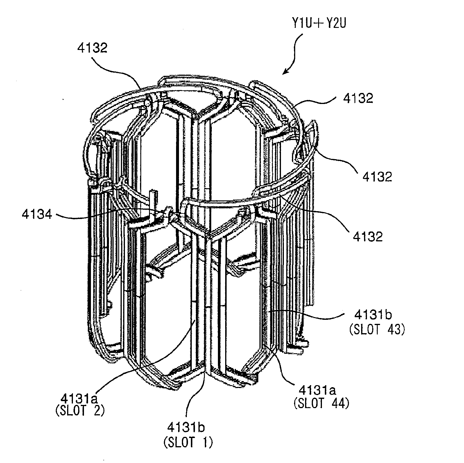
[0118]FIG. 7 is a perspective view of a continuous lap winding stator 4 made of a rectangular wire. The stator iron core 412 is fabricated by laminating punched silicon steel sheets or the like. In the slots (grooves) provided radially on the inner circumference of the cylinder of the iron core, there are incorporated respective stator coils 413, which are lap winding coils made of a rectangular wire and protected as wrapped by insulation paper. The stator coils 413 are fabricated by a plurality of sets of two or more coils that are made continuous through bridge wires 4132.

[0119]The stator shown in FIG. 7 is of 3-phase, 48-slot, NSPP (number of slots per phase and per pole)=2, and 2Y-connection and includes 8 coils of the same phase that are continuous in series. In this case, the number of wire terminals before connection is 12.

[0120]The number of continuously wound coils is not ...

third embodiment

[0133]Now, a third embodiment of the present invention is explained with reference to the attached drawings.

[0134]FIGS. 61A and 61B are cross-sectional views of coils 4131 (4131a, 4131b) with an insulation material 422 on the outer circumference thereof being inserted in a slot 411 defined by the teeth 414. The coils 4131 are formed by winding around in a plurality times a wire 421 made of a rectangular wire having a substantially rectangular cross-section. On the inward side of the stator, there is provided an opening of the slot 411, through which the coils 4131 each having the insulation material 422 are inserted in the back thereof (i.e., in the outward side of the stator, in this case).

[0135]The coil 4131 used in the present embodiment includes hexagonal coils. The coil 4131 is fitted in slots such that one and the other of a pair of opposing linear regions of the hexagonal coils are respectively fitted in a pair of non-adjacent slots that are separated by two or more slots. In...


PUM


Abstract

A rotating electrical machine includes a stator including at least two element coils of the same phase each having a plurality of turns and connected to each other through a coil-to-coil connection wire, the element coils being arranged in adjacent slots, respectively; and a rotor rotatably provided to the stator through a gap. The element coils of the same phase are fitted in the adjacent slots so that wound around portions of the element coils partially overlap each other. The coil-to-coil connection wire connects at a coil end portion conductor wires extending from linear conductor wire portions of innermost wires of the element coils contained in the slots.

Description

INCORPORATION BY REFERENCE[0001]The disclosures of the following priority applications are herein incorporated by reference:[0002]Japanese Patent Application No. 2008-032529 filed Feb. 14, 2008[0003]Japanese Patent Application No. 2008-032527 filed Feb. 14, 2008[0004]Japanese Patent Application No. 2008-032531 filed Feb. 14, 2008BACKGROUND OF THE INVENTION[0005]1. Field of the Invention[0006]The present invention relates to rotating electrical machines such as electric motors and generators.[0007]2. Description of Related Art[0008]The tightening regulations on the exhaust gas emission to cope with soaring oil prices and global warming have activated development of electric vehicles and hybrid electric vehicles that use rotating electrical machines such as motors and generators.[0009]Conventional distributed winding stators for these rotating electrical machines include those stators of a lap winding format as disclosed in, for example, JP H08-298756A and JP 2005-51981A. Such a lap w...

Claims


Application Information

Patent Timeline
IPC IPC(8): H02K3/28H02K3/34
CPCH02K15/066H02K3/28
Inventor HIRAMATSU, HIROMICHIISHIGAMI, TAKASHISAITO, YASUYUKITANAKA, YUICHIRONAKAYAMA, KENICHIMATSUNOBU, YUTAKAHINO, NORIAKI
Owner HITACHI ASTEMO LTD
Why Eureka
Try Eureka