Circuit board test system and test method

a circuit board and test system technology, applied in the direction of electronic circuit testing, measurement devices, instruments, etc., can solve the problems of increasing cost, complication of dut boards, and difficulty in verifying the correct wiring connection between the dut and communication devices, so as to achieve no overhead and no decline in the throughput of mass production

Inactive Publication Date: 2009-10-29
RENESAS ELECTRONICS CORP
View PDF3 Cites 59 Cited by
  • Summary
  • Abstract
  • Description
  • Claims
  • Application Information

AI Technical Summary

Benefits of technology

[0018]In accordance with the present invention, the logical operation of various parts mounted on a circuit board can be checked, the connections can be verified and parameters can be checked at high speed using the measurement function of a tester. Further, in accordance with the present invention, a verifying circuit or a tester signal terminal need not be added to wiring to undergo inspection on a circuit board, no signal degradation at the time of a test operation is induced, characteri

Problems solved by technology

However, in the case of a complicated DUT board on which various communication devices have been mounted, whether the communication devices have the desired functions and whether wiring connections between the DUT and communication devices are correct is difficult to verify because the signal terminals of the communication devices are not connected to the signal terminals of the LSI tester.
Further, the fact that a circuit using the functions of the LSI tester for checking whether the functions of communication devices are correct

Method used


Image

  • Circuit board test system and test method
  • Circuit board test system and test method
  • Circuit board test system and test method

Examples


first exemplary embodiment

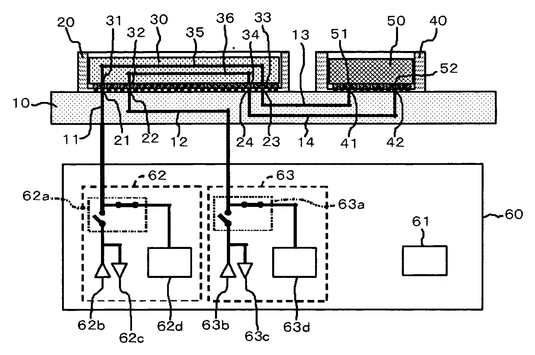
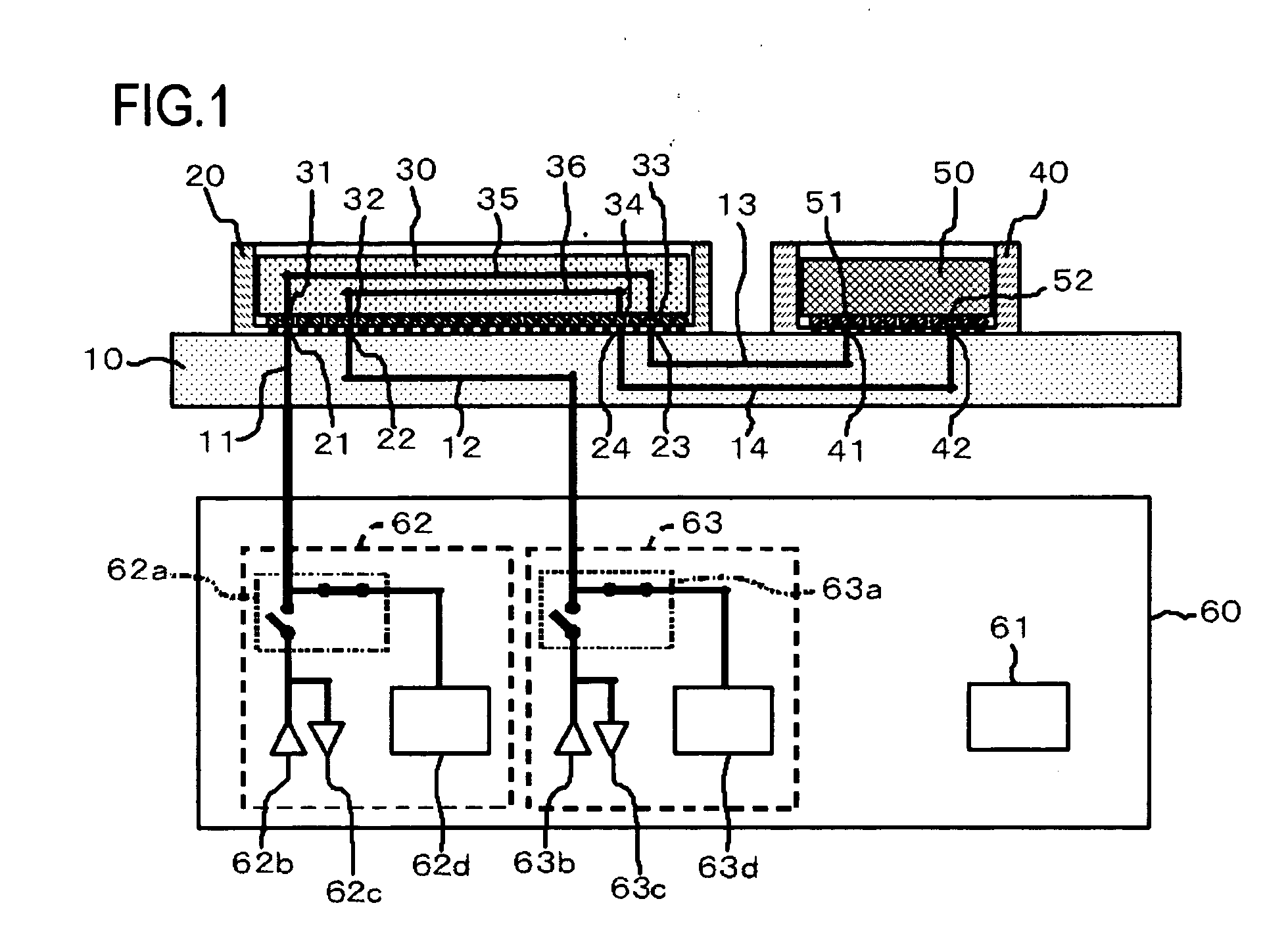
[0029]A circuit board test system according to a first exemplary embodiment of the present invention will now be described. FIG. 1 is a schematic view illustrating the configuration of a circuit board test system according to the first exemplary embodiment.

[0030]The circuit board test system is a system for a DUT board 10 serving as a circuit board. The circuit board 10, on which a shorting board 30 [or DUT (Device Under Test)] and a communication device 50 have been mounted, is electrically connected to an LSI tester 60.

[0031]The DUT board 10 is a circuit board on which the shorting board 30 (or DUT) and communication device 50 are mounted when a test is conducted. Mounted on the DUT board 10 are a socket 20 for removable insertion of the shorting board 30 (or DUT), and a socket 40 for removable insertion of the communication device 50. The DUT board 10 has wires 11, 12 electrically connecting terminals 21, 22, respectively, of socket 20 to the LSI tester 60, and wires 13, 14 elect...

second exemplary embodiment

[0062]A circuit board test system according to a second exemplary embodiment of the present invention will now be described with reference to the drawings, in which FIG. 4 is a schematic view illustrating the configuration of a circuit board test system according to the second exemplary embodiment.

[0063]In the second exemplary embodiment, the DUT board 10 is so adapted that the characteristic of a terminating resistor 15 disposed between the wires 13 and 14 directly underlying the socket 40 is measured. The configuration of this exemplary embodiment is similar to that of the first exemplary embodiment in other respects.

[0064]By inserting the shorting board 30 into the socket 20 with the communication device 50 inserted into the socket 40 of the DUT board 10, as shown in FIG. 4, the wire 13 is connected to the signal terminal testing unit 62 of LSI tester 60 via the socket 20, shorting board 30, wire 11 and external wiring, and the wire 14 is connected to the signal terminal testing ...

third exemplary embodiment

[0066]A circuit board test system according to a third exemplary embodiment of the present invention will now be described with reference to the drawings, in which FIG. 5 is a schematic view illustrating the configuration of a circuit board test system according to the third exemplary embodiment.

[0067]In the third exemplary embodiment, a DUT board 70 has a power-source filter 75 and is equipped with the socket 20 for removable insertion of the shorting board 30. The DUT board 70 has a wire 71 electrically connecting the signal terminal 31 of shorting board 30 and the signal terminal testing unit 62 of LSI tester 60; a wire 72 electrically connecting a coil of the power-source filter 75 and the device power-source unit 61 of LSI tester 60; a wire 73 electrically connecting a capacitor of the power-source filter 75 and the device power-source unit 61; and a wire 74 electrically connecting the signal terminal 33 of shorting board 30 with the coil and capacitor of the power-source filte...


PUM


Abstract

A circuit board system is adapted to check a DUT (Device Under Test) and a communication device on a DUT board, check the connection between DUT and communication device and check connections of parts mounted on DUT board. The system, which tests a circuit board used when a DUT is tested using a tester, has a socket into which DUT is removably inserted; a communication device mounted thereon; first wires electrically connecting first signal terminals of DUT and the tester; and second wires electrically connecting second signal terminals of DUT, which are not electrically connected to the first signal terminals, and signal terminals of the communication device. A shorting board is inserted into the socket in place of DUT when the circuit board is tested, the shorting board having short-circuit wires electrically connecting the first wires and the second wires.

Description

RELATED APPLICATION[0001]This invention is claiming the priority of JP Patent Application No. 2008-044381 filed on Feb. 26, 2008, the entire disclosure thereof being incorporated herein by reference thereto.FIELD OF THE INVENTION[0002]This invention relates to a circuit board test system and method for testing a circuit board used when a device under test is tested using a tester.BACKGROUND[0003]The trend toward higher functionality, larger scale and faster speed in LSI (Large-Scale Integration) has been accompanied by greater difficulty in terms of verifying all of the functions of an LSI chip using just the functions of an LSI tester. Moreover, LSI testers are high in cost. Rather than enhancing the functionality of an LSI tester, therefore, it has been contemplated to lower testing cost by using a DUT (Device Under Test) board that makes it possible to insert a DUT between an LSI tester and a DUT such as an LSI chip. With regard to a DUT board of this kind, there are increasing i...

Claims


Application Information

Patent Timeline
IPC IPC(8): G01R31/02
CPCG01R31/31905
Inventor TAKASE, NOBUYUKI
Owner RENESAS ELECTRONICS CORP
Why Eureka
Try Eureka