
Quadrature modulator and calibration method

a modulator and quadratic wave technology, applied in the field of quadratic wave modulators, can solve the problems of large dynamic range of signals that have to be suppressed, difficult implementation of simple detection schemes, and inability to disclose the rejection of undesired side bands, etc., to achieve the effect of minimizing carrier leakag

Active Publication Date: 2009-10-29
TELEFON AB LM ERICSSON (PUBL)
View PDF6 Cites 16 Cited by
  • Summary
  • Abstract
  • Description
  • Claims
  • Application Information

AI Technical Summary

Benefits of technology

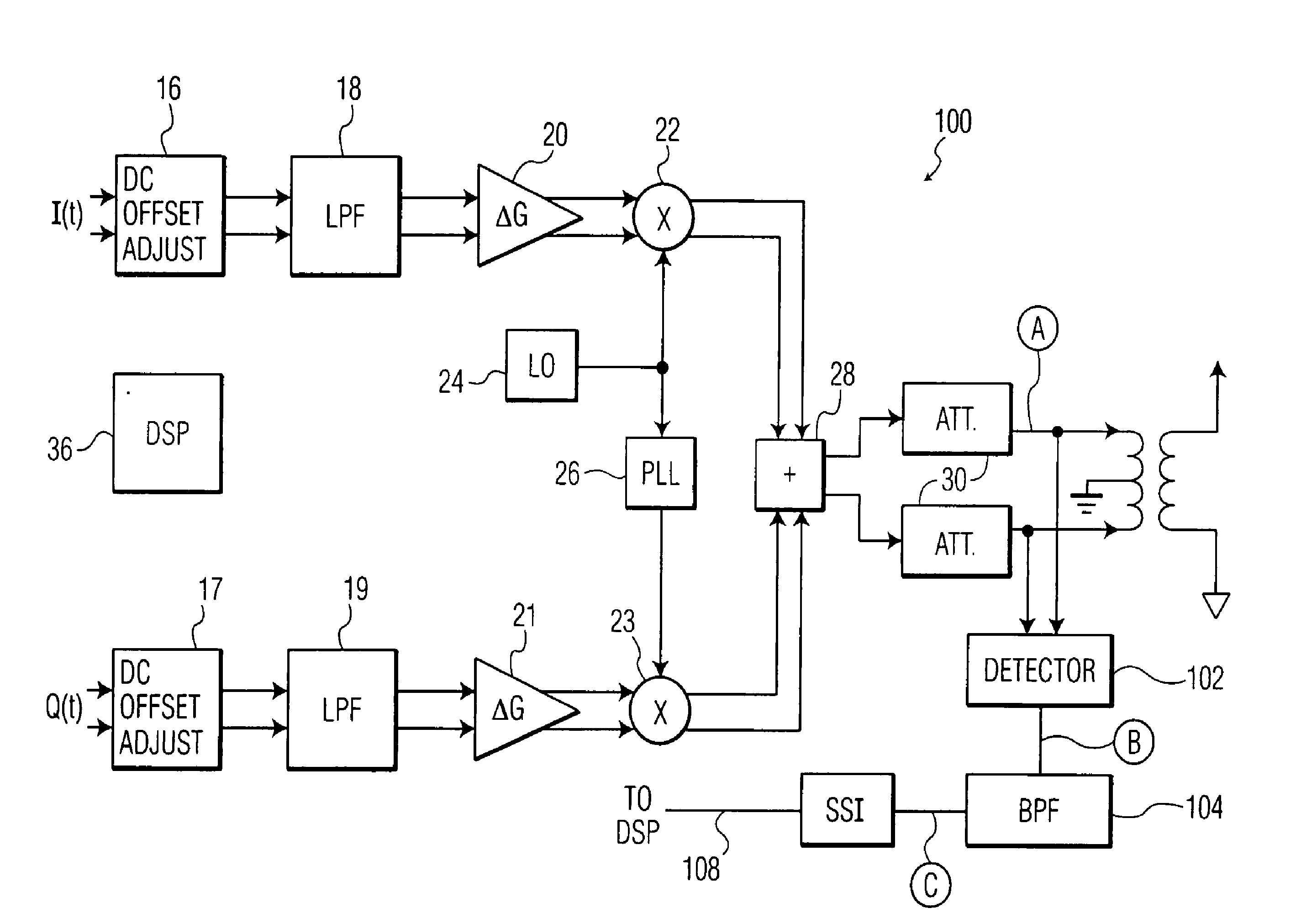
The invention relates to a method and apparatus for calibrating a quadrature modulator. The method involves measuring the level of a local oscillator feedthrough or an undesired sideband frequency component in the output signal, and adjusting the base band dc offsets and gains, as well as the phase shift of the local oscillator signal to minimize the unwanted components. The apparatus includes an in-phase modulation branch and a quadrature modulation branch, with a local oscillator means providing a local oscillator signal to both branches. A band pass filter filters the output signal, and a signal strength indicator circuit measures the strength of the filtered amplitude signal and provides a compensation signal for adjusting the phase shift of the local oscillator and the dc offsets and base band gains of the in-phase and quadrature base band signals. The invention allows for improved performance and stability of the quadrature modulator.

Problems solved by technology

Mohindra does not, however, disclose the rejection of undesired side bands.
Mohindra proposes a simple detection scheme which can be difficult to implement since it does not distinguish between carrier leakage and side-tones or other errors.
Also the large dynamic range of the signals that have to be suppressed require cumbersome and slow “gain-set” and “error-detect” sequences that have to be implemented in software.

Method used


Image

  • Quadrature modulator and calibration method
  • Quadrature modulator and calibration method
  • Quadrature modulator and calibration method

Examples


Embodiment Construction

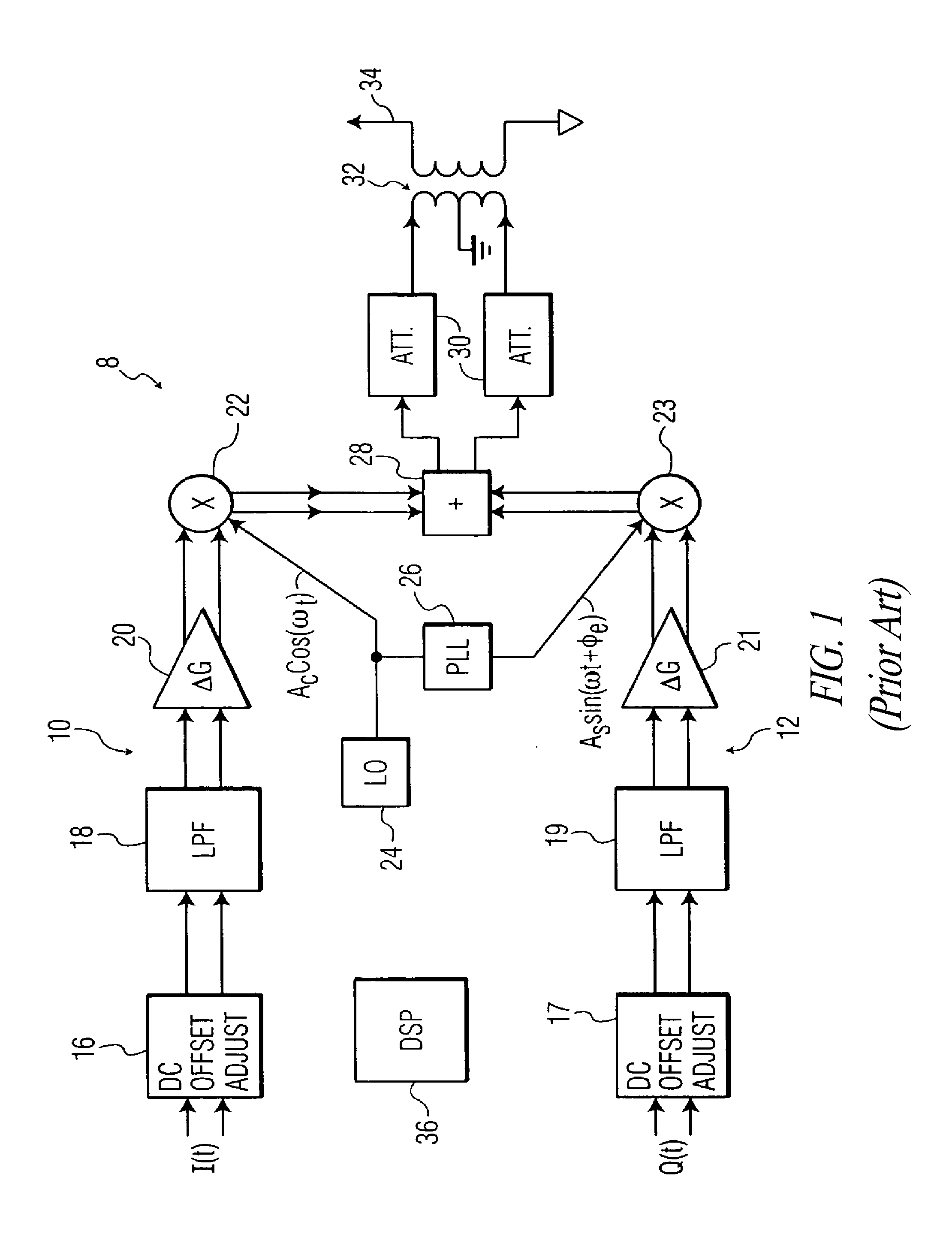
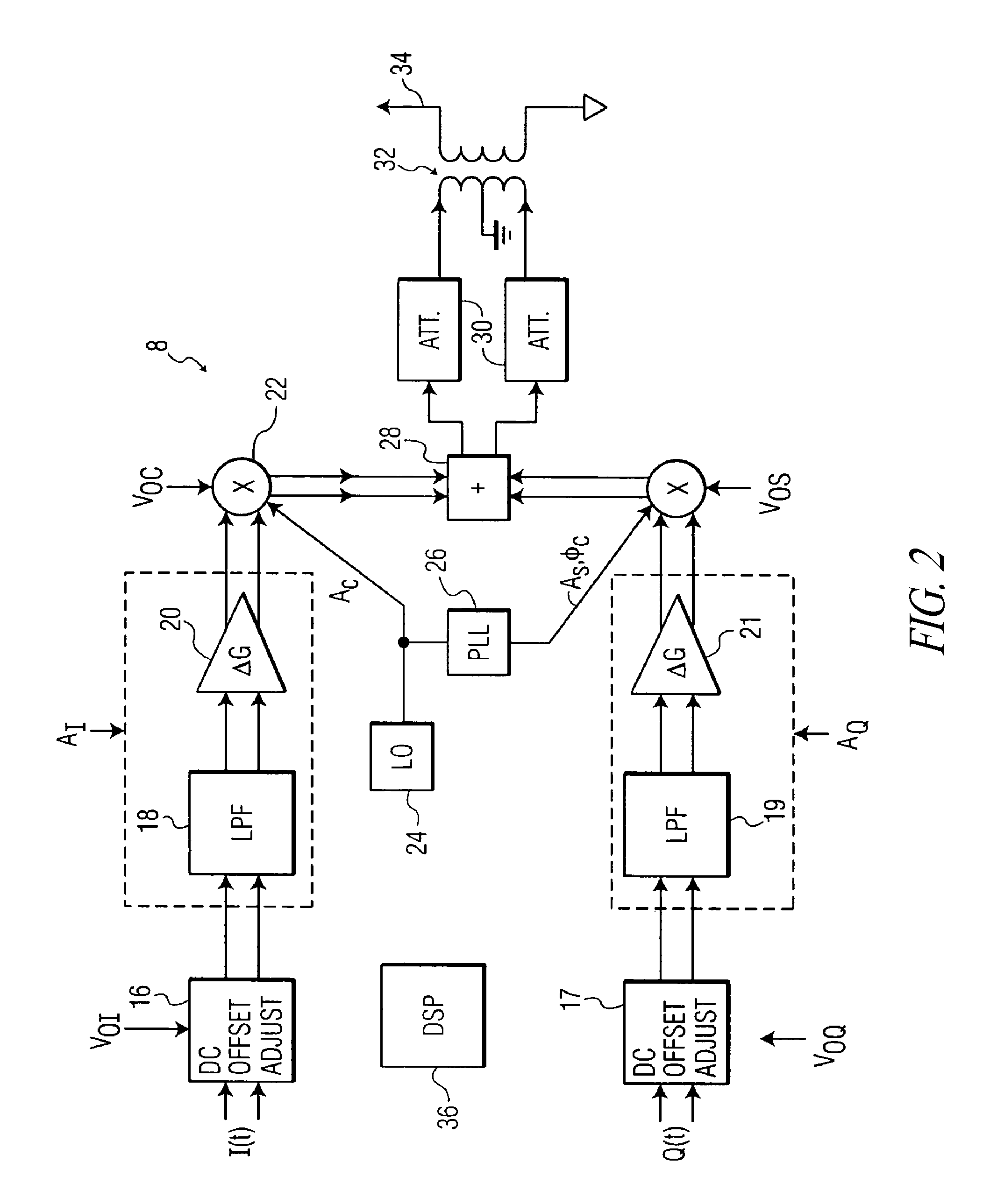
[0021]FIG. 1 shows a quadrature transmitter 8 which includes an in-phase modulation branch 10 and a quadrature modulation branch 12. The in-phase branch 10 includes, in series arrangement, a base band dc offset adjustment block 16, a low pass filter 18, a base band gain adjustment amplifier 20, and mixer 22. The mixer 22 mixes an in-phase signal I(t) (an analog signal carrying digital information) with a sinusoidal carrier signal Ac cos(ωt)generated by a local oscillator (LO) 24. The quadrature phase branch 12 includes, in series arrangement, a dc base band offset adjustment block 17, a low pass filter 19, a gain adjustment amplifier 21, and a mixer 23. The mixer 23 mixes a quadrature signal Q(t) with a carrier signal As sin(ωt+φe) that is generated by the local oscillator 24 and phase shifted 90°, in the ideal case, by a phase shift circuit such as a phase locked loop (PLL) 26. Φe represents the phase shift error.

[0022]The outputs of the mixers 22 and 23 are summed by a summer 28, ...


PUM


Abstract

A quadrature modulator and a method of calibrating same by applying a first test tone signal to an in-phase modulation branch input of the modulator and a ninety degree phase-shifted version of the first test tone signal to a quadrature modulation branch input of the modulator. The carrier leakage level in an output signal of the modulator is measured and in response base band dc offset voltages are adjusted to minimize the carrier leakage. A second test tone signal is applied to the in-phase modulation branch input and a ninety degree phase-shifted version of the second test tone signal to the quadrature modulation branch input. The level of an undesired upper sideband frequency component in the output signal is measured and in response base band gains the in-phase and quadrature modulation branches and a local oscillator phase error are adjusted to minimize the undesired side band.

Description

BACKGROUND[0001]1. Technical Field[0002]The invention relates to a quadrature modulator, a radio communication device comprising a quadrature modulator, and a method of calibrating the quadrature modulator or radio communication device.[0003]2. Description of the Related Art[0004]In a quadrature modulator, carrier leakage reduction and side band rejection have typically been carried out using one of two conventional methodologies. One of these methodologies depends on circuit matching, dynamic swapping, and the use of polyphase filters, all of which are carried out in the design phase. The second type of methodology deals with an imperfect chip but relies on user calibration methods while the chip is in use.[0005]One example of the second methodology is disclosed in U.S. Pat. No. 6,169,463 to Mohindra et al. which discloses a quadrature modulator with set and forget carrier leakage compensation. Upon the power-up of the quadrature modulator, carrier leakage is measured in the in-pha...

Claims


Application Information

Patent Timeline
Patent Type & Authority Applications(United States)
IPC IPC(8): H04L27/34H03C3/40
CPCH04L27/364H03C3/406H04L27/36H03C3/40
Inventor PARSA, ALIFOTOWAT-AHMADY, ALIFAGHFURI, ALIJENABI, MAHTARIOU, EMMANUELHAHN, WILHELM STEFFEN
Owner TELEFON AB LM ERICSSON (PUBL)
Learn More