Optical transmitting apparatus

a technology of optical transmission apparatus and optical transmission, which is applied in the direction of optics, electromagnetic transceivers, instruments, etc., can solve the problems of lowering control stability, low sensitivity of monitoring signals, and reducing control accuracy

Active Publication Date: 2009-10-29
FUJITSU LTD
View PDF5 Cites 33 Cited by
  • Summary
  • Abstract
  • Description
  • Claims
  • Application Information

AI Technical Summary

Benefits of technology

[0010]It is an object of the present invention to at least solve the above problems in the conventional technologies.
[0011]An optical transmitting apparatus according to one aspect of the invention includes: a modulating unit that branches an input light and performs independent phase modulation to branched optical signals of arms; a phase adjusting unit that changes a phase difference between the optical signals of respective arms according to a control signal; a combining unit that combines modulated lights having the phase difference; an acquiring unit that acquires a positive-phase signal and a negative-phase signal from the combining unit; a subtracting unit that obtains a difference between the positive-phase signal and the negative-phase signal acquired by the acquiring unit; a detecting unit detecting a power of a differential signal from subtraction by the subtracting unit; and a control unit that changes the control signal according to signal component intensity detected by the detecting unit.
[0012]An optical transmitting apparatus according to one aspect of the invention includes: a modulating unit that branches an input light and performs independent phase modulation to branched optical signals of arms; a phase adjusting unit that changes a phase difference between the opti...

Problems solved by technology

However, the above conventional technology has problems of a low sensitivity of a monitoring signal and lowering of control stability, depending on characteristics of constituent components such as an output power of an LD, a loss of the modulator, and a light-rec...

Method used


Image

  • Optical transmitting apparatus
  • Optical transmitting apparatus
  • Optical transmitting apparatus

Examples


first embodiment

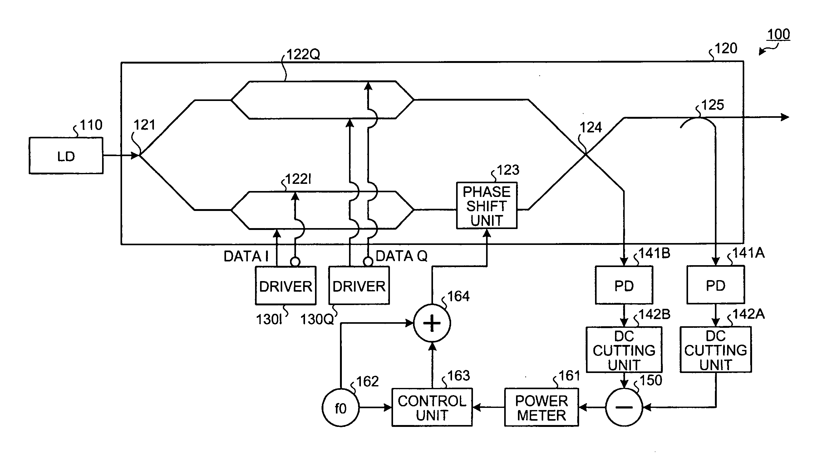
[0098]As above, the optical transmitting apparatus detects the differential signal obtained by a subtracting operation between the negative-phase signal and the positive-phase signal, and is capable of sharpening the change of the monitoring signal for the deviation of the phase difference between the arms. This enables, by monitoring the low-frequency signal component corresponding to the power change of the differential signal, improving the sensitivity of the control monitoring signal monitored by the control unit 163 and detecting the optimum point of the phase difference with high accuracy. For this reason, stabilization of the control is improved.

[0099]When the phase difference between the arms deviates from the optimum point, power of the differential signal changes over the wide band including a lower band. Therefore, circuits up to the control unit 163 are not required to employ circuits of an especially wide band but may employ general-use circuits. This enables achieving...

second embodiment

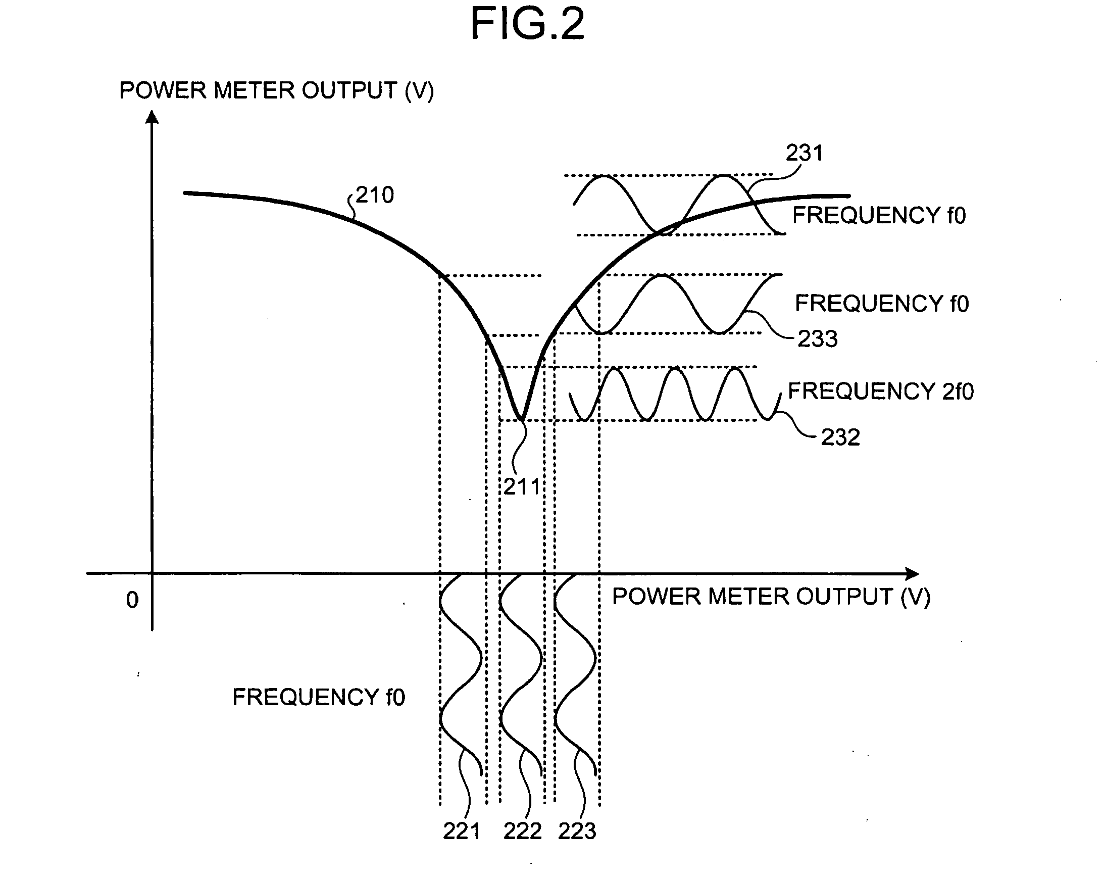
[0103]FIG. 12 is a graph of the output of the power meter depicted in FIG. 11. In FIG. 12, with respect to the same part as depicted in FIG. 6, description thereof will be omitted, with the same reference numeral given thereto. As depicted by the dotted lines 611 and 612 and the solid lines 621 and 622, in the optical transmitting apparatus 100 the amount of output change of the power meter 161 against the amount of phase deviation from the optimum point nπ / 2 (n is an arbitrary odd number) of the phase difference between the arms is substantially the same irrespective of values of the characteristic Tr / Tf.

[0104]Conventionally, when the characteristic Tr / Tf was 10 ps, the change of the output of the power meter 161 against the change of the phase deviation amount was gently-sloping (see dotted line 611). By contrast, according to the optical transmitting apparatus 100, even when the characteristic Tr / Tf is 10 ps, the change of the output of the power meter 161 against the ch...

third embodiment

[0110]As depicted by the solid line 1410 and the solid line 1420, the optical transmitting apparatus 100 is capable of increasing an absolute value of the output of the power meter 161 twice as much as that of the conventional optical transmitting apparatus. Therefore, the optical transmitting apparatus 100 is capable of detecting the deviation of the phase difference between the arms of the LN modulator 120 at high sensitivity at the control unit 163.

[0111]FIG. 15 is a graph of the output (with DC component) of the power meter depicted in FIG. 13. In FIG. 15, with respect to the same part as depicted in FIG. 14, description thereof will be omitted, with same reference numeral given thereto. FIG. 15 depicts the output of the power meter 161 when the optical transmitting apparatus 100 is not provided with the DC cutting part 142A or the DC cutting part 142B.

[0112]In this case, since a DC component is not removed by the DC cutting part 142A or the DC cutting part 142B, the positive-p...


PUM


Abstract

An optical transmitting apparatus includes a modulating unit that branches an input light and performs independent phase modulation to branched optical signals of arms, a phase adjusting unit that changes a phase difference between the optical signals of respective arms according to a control signal, a combining unit that combines modulated lights having the phase difference, an acquiring unit that acquires a positive-phase signal and a negative-phase signal from the combining unit, a subtracting unit that obtains a difference between the positive-phase signal and the negative-phase signal acquired by the acquiring unit, a detecting unit detecting a power of a differential signal from subtraction by the subtracting unit, and a control unit that changes the control signal according to signal component intensity detected by the detecting unit.

Description

CROSS-REFERENCE TO RELATED APPLICATIONS[0001]This application is based upon and claims the benefit of priority from the prior Japanese Patent Application No. 2008-109327, filed on Apr. 18, 2008, the entire contents of which are incorporated herein by reference.BACKGROUND[0002]1. Field[0003]The disclosure relates to an optical transmitting apparatus that modulates light and a control method of the optical transmitting apparatus.[0004]2. Description of the Related Art[0005]Toward a higher capacity and a longer distance of an optical transmission system, evaluation is being made of various modulation systems for transmission of an optical signal. Research and development are being made of the optical transmission systems using various phase modulation systems such as a CSRZ (Carrier Suppressed RZ) modulation system, an optical duobinary modulation system, a DPSK (Differential Phase Shift Keying) system, a SSB (Single Side Band) modulation system, and a DQPSK (Differential Quadrature PS...

Claims


Application Information

Patent Timeline
IPC IPC(8): H04B10/04G02F1/035H04B10/40H04B10/07H04B10/50H04B10/516H04B10/556H04B10/60H04B10/61
CPCH04B10/5051H04B10/5057H04B10/5053
Inventor AKIYAM, YUICHIMIYATA, HIDEYUKIMIZUGUGHI, NORIAKI
Owner FUJITSU LTD
Why Eureka
Try Eureka