Fan blade

a technology of fan blades and blades, applied in the direction of machines/engines, mechanical equipment, liquid fuel engines, etc., can solve the problems of blade damage, blade efficiency drop at cruise, and increase in efficiency at cruise, so as to reduce engine noise

Inactive Publication Date: 2009-10-29
ROLLS ROYCE PLC
View PDF6 Cites 17 Cited by
  • Summary
  • Abstract
  • Description
  • Claims
  • Application Information

AI Technical Summary

Benefits of technology

[0015]The fan case may have an acoustic liner at the interface between the sealing element and the fan case. This can reduce engine noise, and is possible because an abradable liner at this position is not needed.

Problems solved by technology

This causes an efficiency drop at cruise.
However, for every rub event, the efficiency drop at cruise increases.
Further, such contacts carry the risk of damaging the blade, and reducing its longevity.
This risk can be higher with a blade formed of composite material, which may be susceptible to delamination or matrix damage under frictional loading.
Ultimately, damage from excessive rubbing contacts accumulating over time may cause premature blade failure, particularly in blades formed of composite material.

Method used


Image

  • Fan blade
  • Fan blade
  • Fan blade

Examples


Embodiment Construction

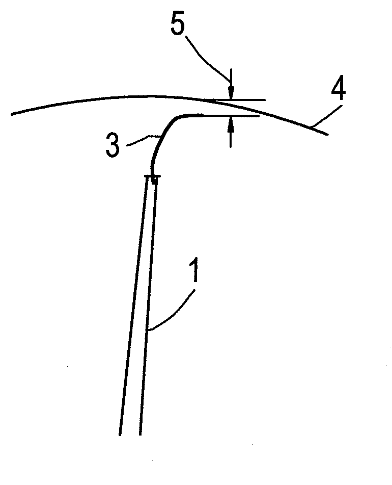
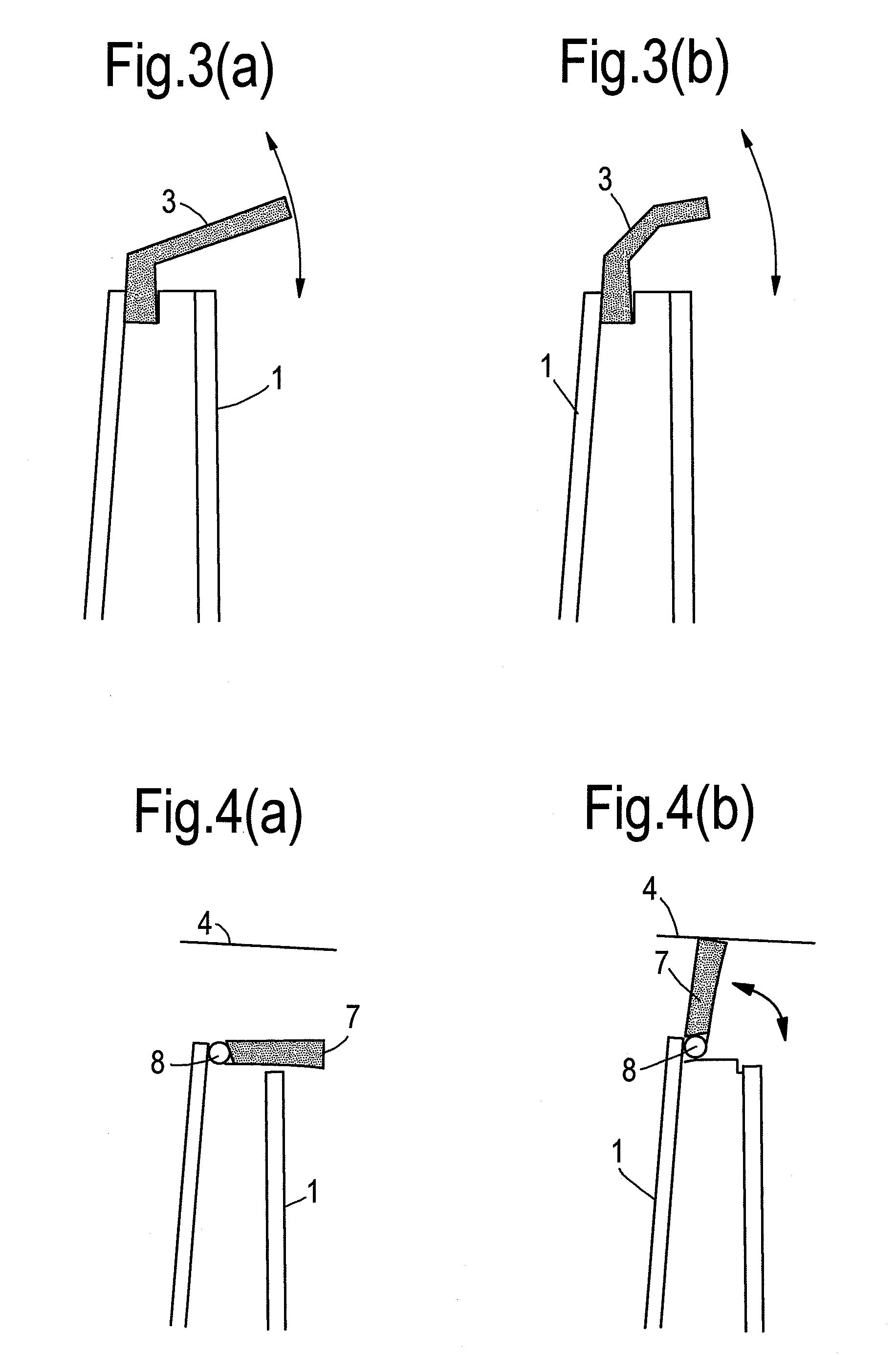
[0024]FIG. 1 shows schematically the tip of a fan blade 1. Slotted into a keyway 2 which runs along the radially outer edge of the blade is a strip sealing element 3 formed of a flexible material, such as plastic, rubber (e.g. silicone rubber) or coated metal foil. The sealing element can be removably replaceable when worn or damaged.

[0025]The keyway 2 can be formed in the body of a composite or a metallic blade, or can be formed by a separate part, e.g. facing side plates, attached to the tip of such a blade.

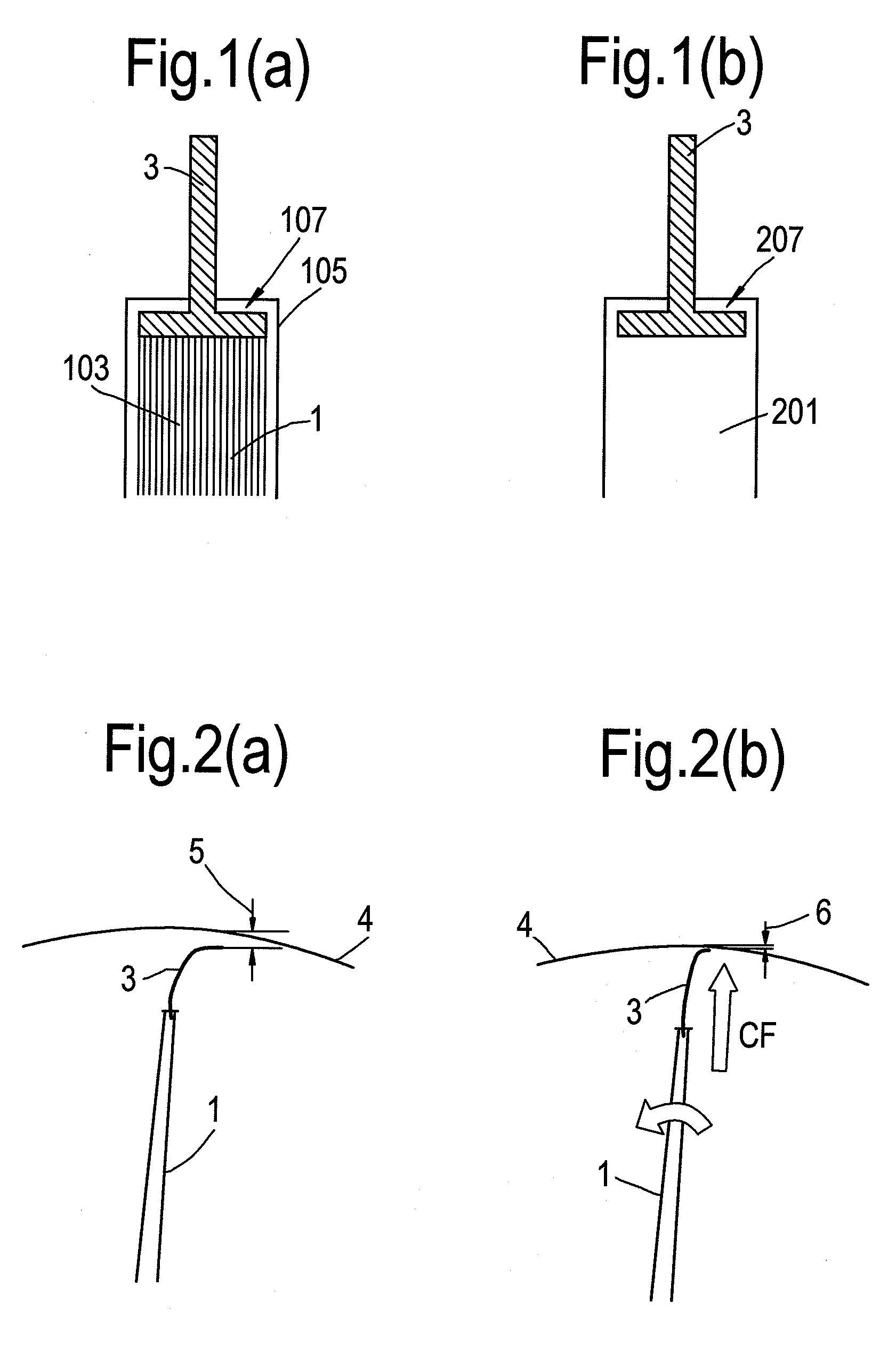
[0026]FIGS. 2(a) and (b) show schematically the operation of the sealing element 3. In

[0027]FIG. 2(a), the engine is stationary. Sealing element 3 has a curved cross-section profile, and there is a relatively large cold build clearance 5 between the radially outer edge of the sealing member 3 and the fan case 4. In FIG. 2(b), the blade is now rotating in the direction indicated by the curved arrow. A centrifugal force (CF) straightens out the profile of the sealing element so t...


PUM


Abstract

A fan blade for the fan of a gas turbine engine has a radially outer tip portion which, in use, is adjacent to a fan case of the engine. The tip portion includes a movable sealing element for sealing a gap between the tip portion and the fan case. The sealing element movably adapts to changes in the spacing of the gap to maintain a seal between the tip portion and the fan case.

Description

CROSS REFERENCE TO RELATED APPLICATION[0001]This application is entitled to the benefit of British Patent Application No. GB 0807358.7, filed on Apr. 23, 2008.FIELD OF THE INVENTION[0002]The present invention relates to a fan blade for the fan of a gas turbine engine.BACKGROUND OF THE INVENTION[0003]The fan of a gas turbine engine comprises a cascade of circumferentially spaced an blades mounted at their radially inward ends on a disc and extending radially outwardly towards a fan case. To minimise aerodynamic losses and maintain the performance and stability of the fan blades, it is important to reduce leakage of air between the tips of the fan blades and the case. To this end, it is usual to have a close clearance between the tips and the case.[0004]A conventional method of achieving a close clearance is to use fan track liners. These are positioned outboard of the fan blades on the fan case, and typically comprise an abradable liner supported by an aluminium honeycomb structure. ...

Claims


Application Information

Patent Timeline
Patent Type & Authority Applications(United States)
IPC IPC(8): F01D11/08F01D25/00
CPCF01D11/12F04D29/164F05D2220/323F05D2220/36F05D2240/307F05D2240/55
Inventor BOTTOME, KRISTOFER JOHN
Owner ROLLS ROYCE PLC
Why Eureka
Try Eureka