
Adjacent level cervical spine plate

a cervical spine and plate technology, applied in the field of anterior cervical tension bands or surgical plate systems, can solve the problems of high risk of vertebrae rupture, high probability of damage to vertebrae and surrounding soft tissue, and difficult to remove the installed plate, and achieve the effect of easy connection with the backbone and easy extension along the spin

Active Publication Date: 2009-10-29
FLANDRY JR ROBERT E
View PDF13 Cites 6 Cited by
  • Summary
  • Abstract
  • Description
  • Claims
  • Application Information

AI Technical Summary

Benefits of technology

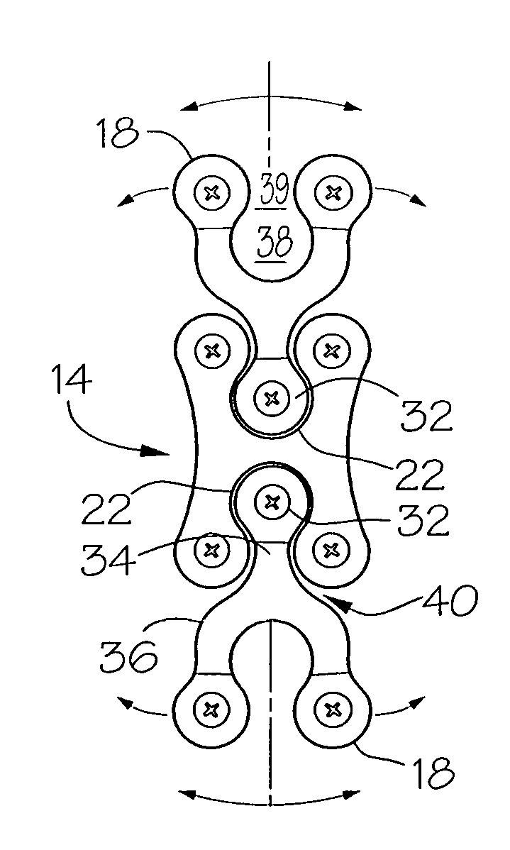
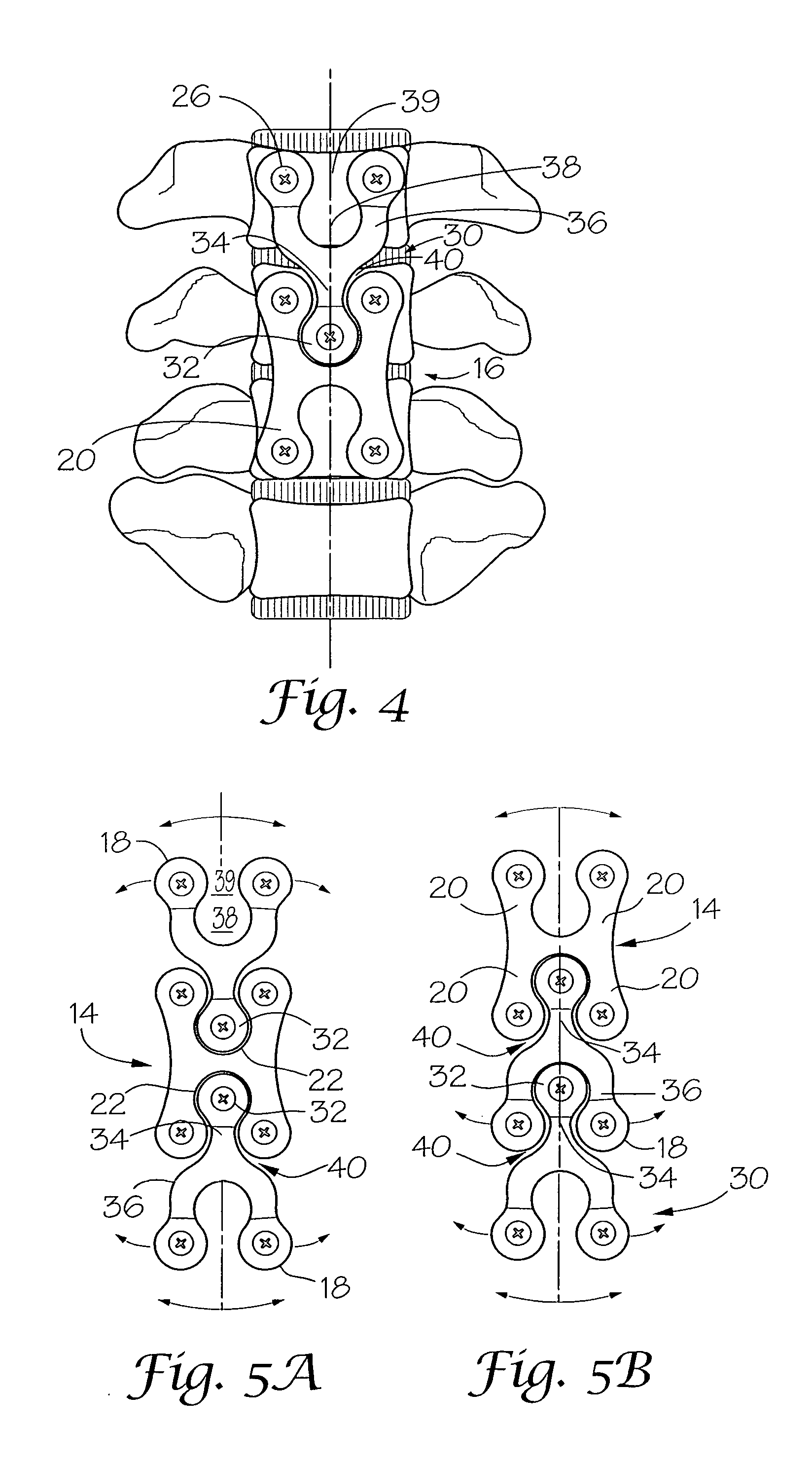
[0016]The channels and the bays are formed of a first size while the heads and necks are formed of a second and smaller size. This structure allows the H-shaped plate to be positioned over adjacent vertebrae, aligned as best possible with the longitudinal axis of the backbone and secured by screws with the associated adjacent vertebrae. The head and neck of the Y-shaped connector may then be positioned in a first of the bays and channels of the H-shaped connector with the head positioned over one of the first of the secured vertebrae and with the bay and channel forming legs positioned over a third and adjacent vertebrae. The Y-shaped surgical plate is adjusted laterally to position as best as possible the bay centrally of the longitudinal axis of the backbone and secured with the adjacent vertebrae. This plate system allows each additional Y-shaped surgical plate to be adjusted and aligned along the longitudinal axis of the backbone.

Problems solved by technology

Because of growth, as above referred to, it is extremely difficult to remove the installed plate.
Further, damage to the vertebrae and surrounding soft tissue is a high probability during such a removal process.
This process raises the risk of vertebrae rupture due to the size of the vertebrae and the many screws which are longitudinally spaced and inserted into each vertebrae.
Again, a problem exists.
This is extremely difficult due to limited exposure to the entire spine, the particular anatomy or the configuration of each vertebrae.
These references specifically do not allow lateral adjustment of an additional or joining plate relative to the previously installed plate.

Method used


Image

  • Adjacent level cervical spine plate
  • Adjacent level cervical spine plate
  • Adjacent level cervical spine plate

Examples


Embodiment Construction

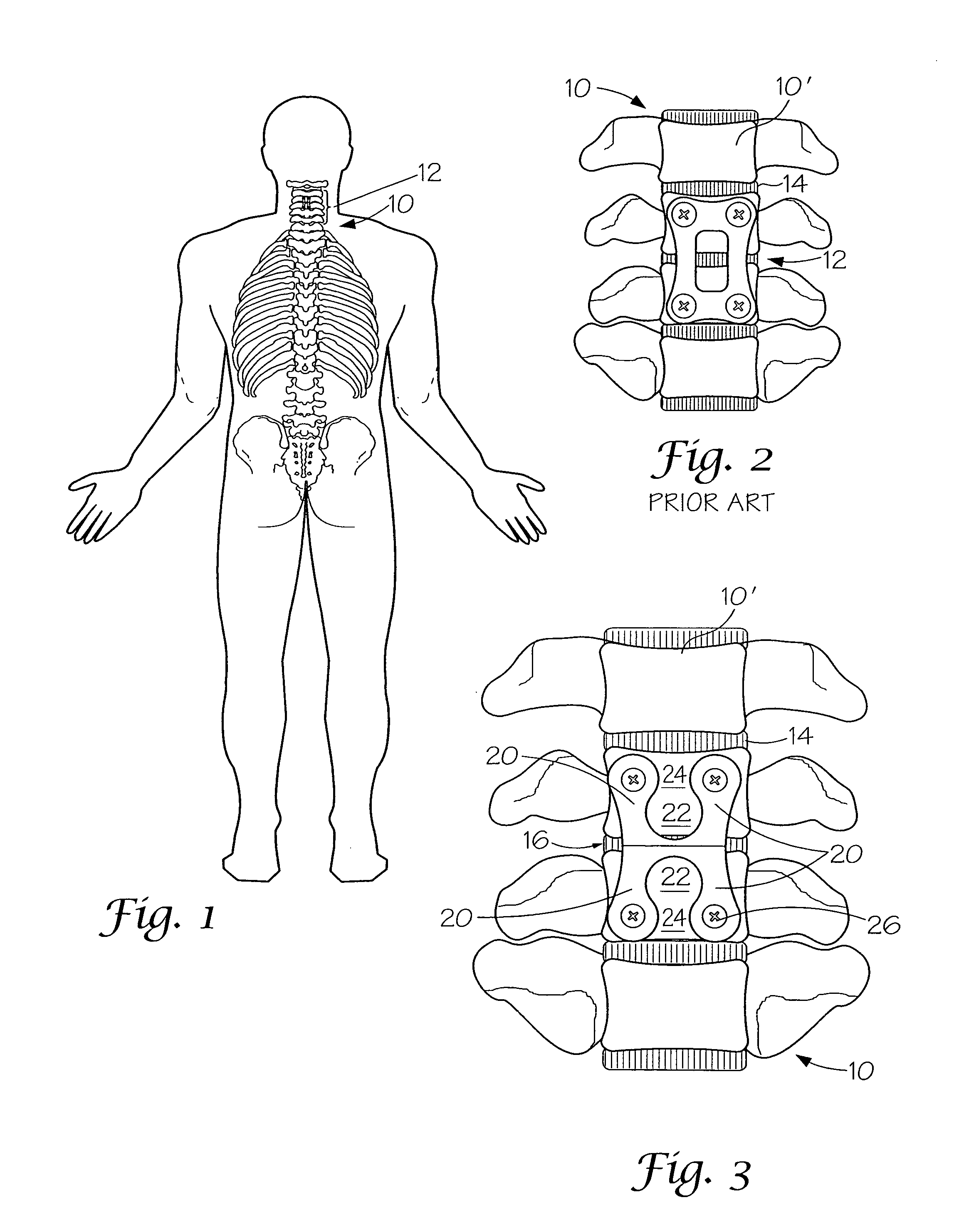
[0026]Turning now to the drawings, FIG. 1 is a diagrammatic view of the vertebrae 10 in which an anterior cervical fusion has been performed by the installation of a surgical plate 12, stabilizing and separating the adjacent vertebrae. Generally, these surgical plates have been formed as a single unit capable of being connected with a pair of adjacent vertebrae 10 as shown in FIG. 2.

[0027]Turning now to FIGS. 3 and 4, Y-shaped surgical plates 30 and H-shaped surgical plates 12 of the invention are formed of metal to be about 3 cm or greater in length and about 2 cm in width. Each surgical plate is provided with a receiver in the form of bays 22 and 38, which are about 9 mm in diameter. The width of head 22 is about 2 mm less. Channels 24 and 39 are about 5 mm while neck 34 is between about 2 mm and 4 mm. Both H and Y-shaped surgical plates are generally arcuate widthwise as shown in FIG. 6 to generally conform with the surface of the vertebrae. The smaller neck and head fit into the...


PUM


Abstract

A surgical plate system for stabilizing vertebrae of a backbone which includes a first surgical plate, which when connected to adjacent vertebrae of a backbone is constructed to allow attachment with an additional plate which is then interconnectable with a first of the adjacent vertebrae and a third adjacent vertebrae. The connection between the adjacent surgical plates is constructed to allow lateral adjustment between the plates prior to the plates being secured with the vertebrae.

Description

BACKGROUND OF THE INVENTION[0001]The instant invention is directed to an anterior cervical tension band or surgical plate system with the capability of plates interconnecting at spaced time periods to stabilize additional vertebrae which have become diseased. This procedure is generally old and known, as is illustrated by the patent to Dinh, et al U.S. Pat. No. 7,186,254 and the publication to Bert, No. 2006 / 0116681. Neither of these publications recognizes or deals with the problem solved by the instant invention.[0002]In practice, vertebrae separated by a damaged disk must be maintained, separated and be stationarily stabilized. To do this a surgical plate is positioned over a graft and secured by screws with the adjacent vertebrae. Over time, bone and cartilage may grow over, adhere to and cover the surgical plate.[0003]It is common for the disk separating a vertebrae adjacent the stabilized vertebrae to break down or become diseased, i.e. up to 25% over a five-year period. When ...

Claims


Application Information

Patent Timeline
IPC IPC(8): A61B17/56A61B17/80
CPCA61B17/7059
Inventor FLANDRY, JR., ROBERT E.
Owner FLANDRY JR ROBERT E
Learn More