
Travel control device

a control device and travel control technology, applied in process and machine control, instruments, navigation instruments, etc., can solve the problems of difficult prior art to improve the average mileage and average speed of the vehicle group, and the vehicle cannot be allowed to run, so as to improve the average mileage and average speed, reduce the average required time, and improve the effect of traffic flow

Active Publication Date: 2009-10-29
TOYOTA JIDOSHA KK
View PDF7 Cites 23 Cited by
  • Summary
  • Abstract
  • Description
  • Claims
  • Application Information

AI Technical Summary

Benefits of technology

[0003]However, the prior art aims at smoothly forming a vehicle group and thus cannot allow the vehicle to run in response to a running mode required by the driver. For example, the prior art forms a vehicle group even when it is desirable to reach a destination as soon as possible, whereby the vehicle does not always arrive at the destination sooner. It is also difficult for the prior art to improve the average mileage and average speed of the vehicle group.

Problems solved by technology

However, the prior art aims at smoothly forming a vehicle group and thus cannot allow the vehicle to run in response to a running mode required by the driver.
It is also difficult for the prior art to improve the average mileage and average speed of the vehicle group.

Method used


Image

  • Travel control device
  • Travel control device
  • Travel control device

Examples


first embodiment

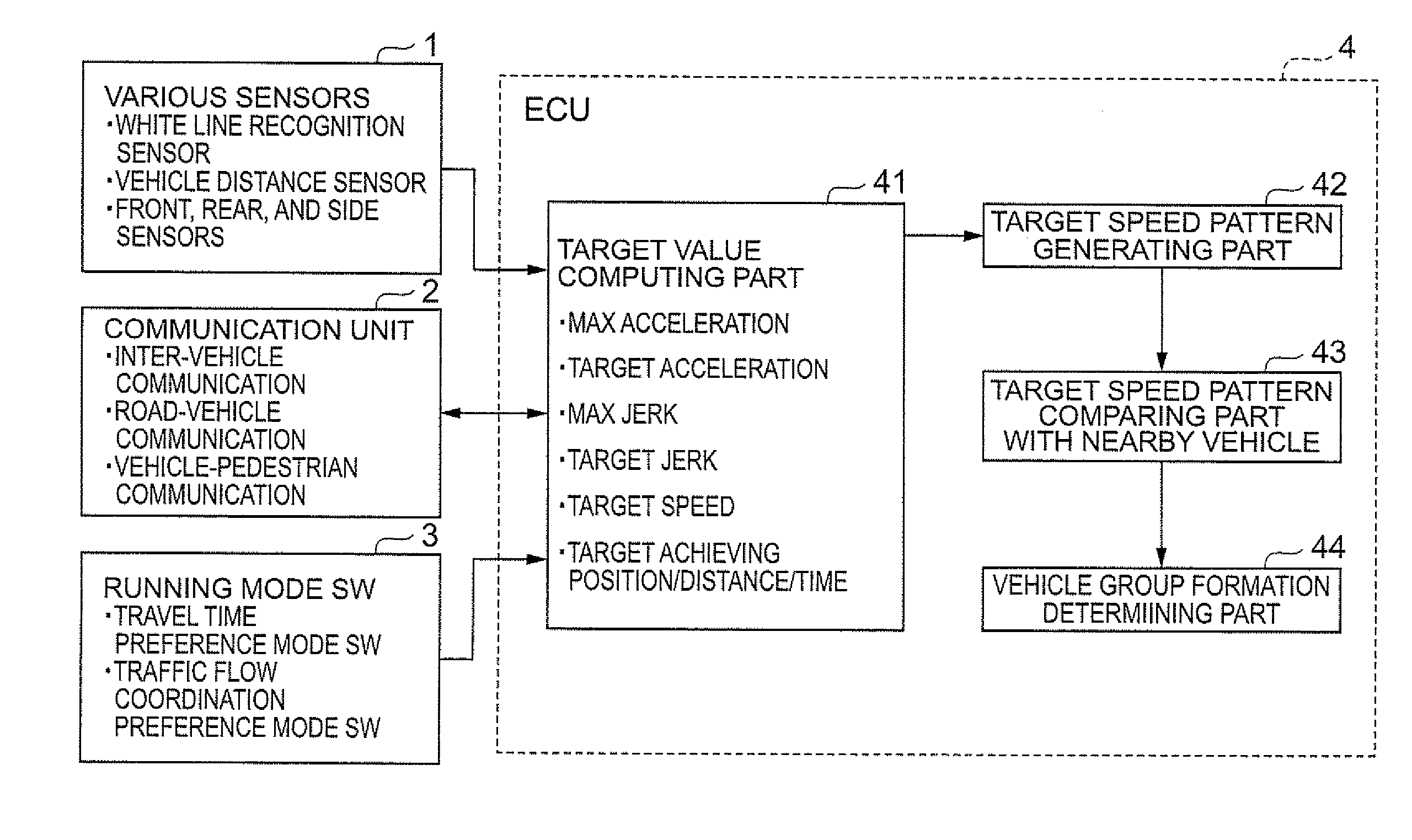
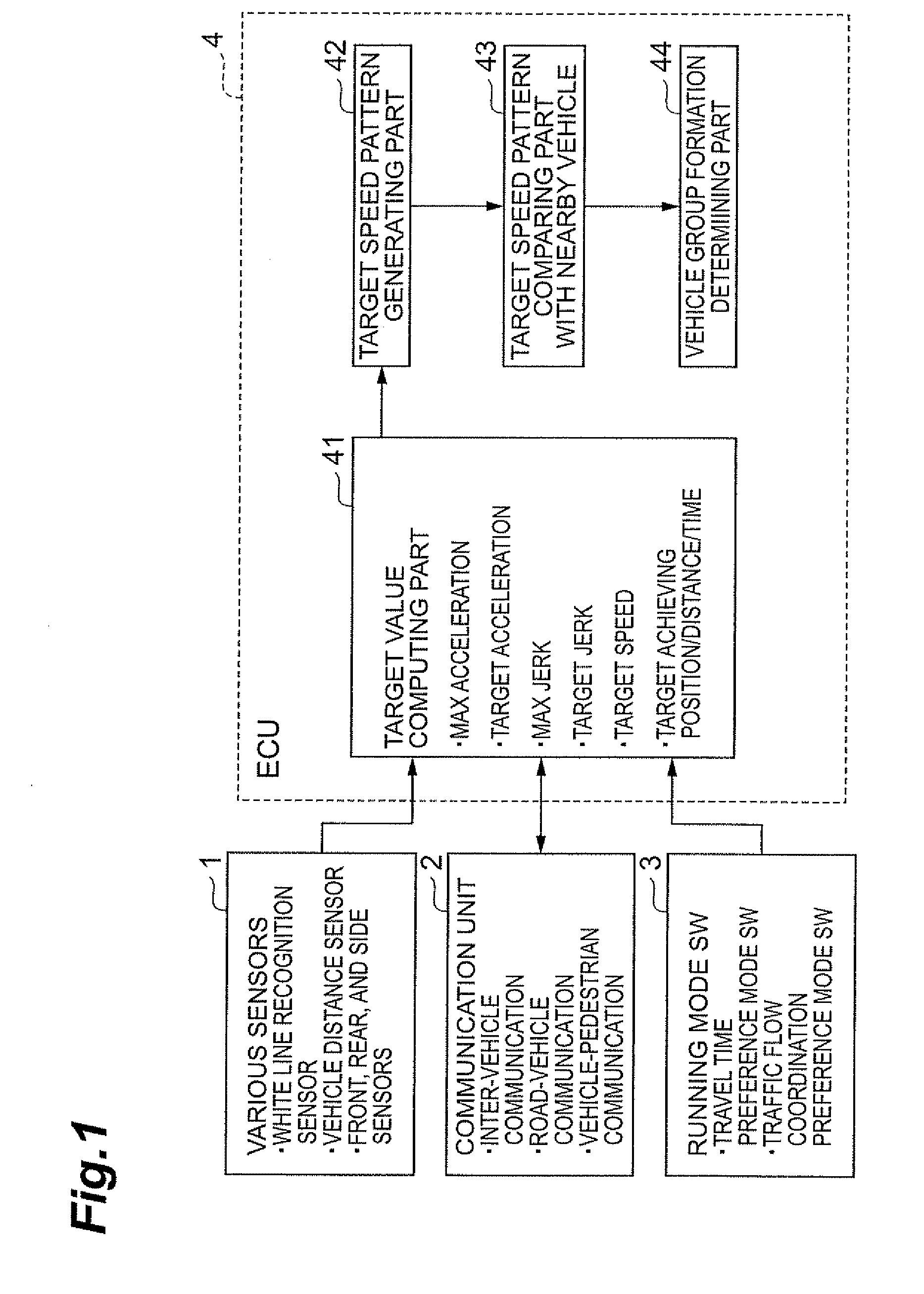
[0030]FIG. 1 is a schematic view showing a hardware structure of the running control apparatus in accordance with the first embodiment of the present invention. The running control apparatus in accordance with this embodiment comprises various sensors 1, a communication unit 2, a running mode input switch 3, and an ECU 4. Here, the ECU (Electronic Control Unit) is a computer for automobile devices to be electronically controlled, which comprises a CPU (Central Processing Unit), a ROM (Read Only Memory), a RAM (Random Access Memory), I / O interfaces, and the like.

[0031]The various sensors 1 include a white line recognition sensor for recognizing white lines painted on roads, a vehicle distance sensor for measuring the distance between the own vehicle and another vehicle, and front, rear, and side sensors for recognizing objects in front and rear and on the sides of the own vehicle and have functions of inputting information required for automatic running. For example, the white line r...

second embodiment

[0076]The running control apparatus and vehicle group forming system in accordance with the second embodiment of the present invention will now be explained.

[0077]The running control apparatus and vehicle group forming system in accordance with the second embodiment are constructed substantially the same as those in accordance with the first embodiment except that vehicle groups are formed in consideration of a route to run. In the following, differences from the first embodiment will mainly be explained.

[0078]FIG. 6 is a schematic view showing a hardware structure of the running control apparatus in accordance with the second embodiment, The running control apparatus in accordance with this embodiment is constructed substantially the same as that in accordance with the first embodiment except that the target speed pattern generating part 42, target speed pattern comparing part 43, and running mode input switch 3 in the first embodiment are replaced by an action plan generating part...


PUM


Abstract

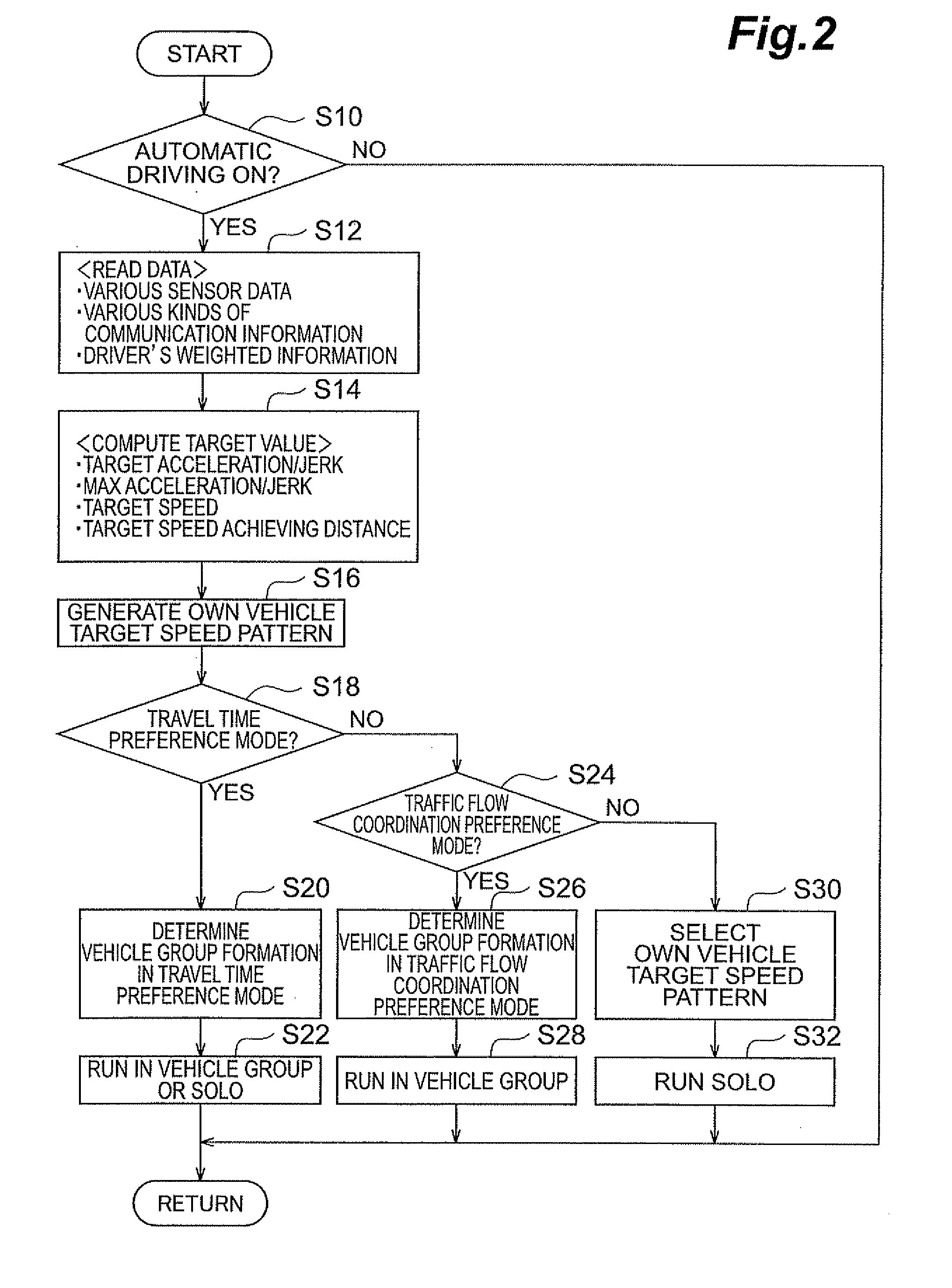
Information for generating a target speed pattern is computed from information acquired from various sensors and a running mode input switch, so as to generate the target speed pattern (S16). A process for determining whether to form a vehicle group or not calculates the difference between the target vehicle pattern of the own vehicle and a target speed pattern of another vehicle or vehicle group obtained through inter-vehicle communication, so as to determine whether to form the vehicle group or not (S22, S28, S32). This can determine whether to run solo or form a vehicle group according to a driver's demand.

Description

TECHNICAL FIELD[0001]The present invention relates to a running control apparatus.BACKGROUND ART[0002]An idea has conventionally been proposed in which vehicles running on a road and the like form a group such as to construct an array also known as platoon. Running in a group is expected to be effective in improving mileage and traffic flow efficiency, alleviating driving load, increasing moving speed, and so forth. Known as an apparatus for forming such a vehicle group is one computing a degree of similarity between vehicle information of a vehicle and vehicle information of another vehicle or vehicle group and forming a group with a vehicle or vehicle group whose similarity is at a set value or greater (see, for example, Japanese Patent Application Laid-Open No. 10-261195). This apparatus uses destinations, vehicle position information, engine output, torque characteristics, acceleration performances, brake characteristics, and the like as vehicle information to be compared betwee...

Claims


Application Information

Patent Timeline
Patent Type & Authority Applications(United States)
IPC IPC(8): G06F7/00
CPCG08G1/16G08G1/22G08G1/163
Inventor NIKI, KEITAROSHIDA, MITSUHISADOI, TOMOYUKISATO, KUNIHITO
Owner TOYOTA JIDOSHA KK
Learn More